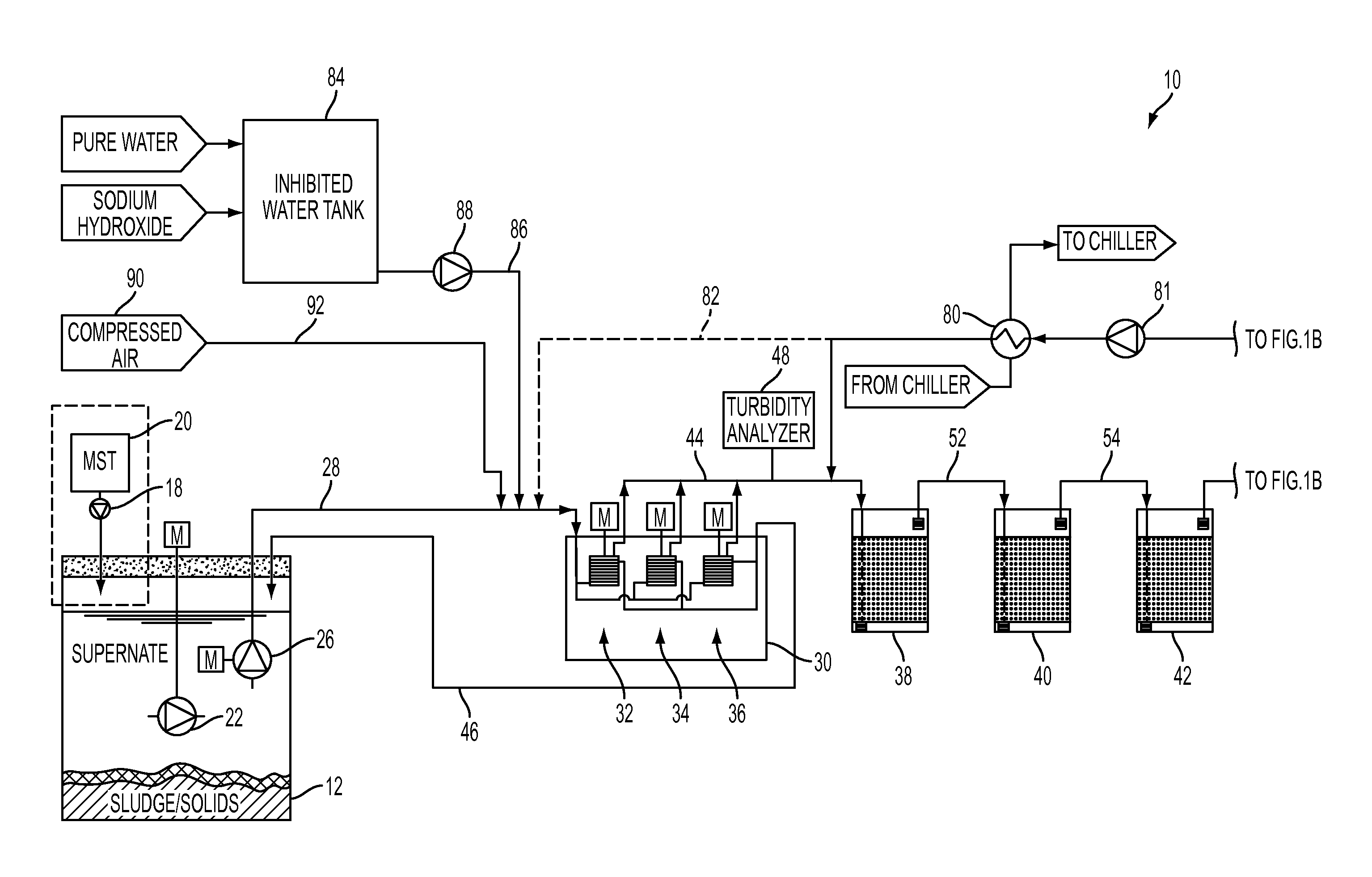
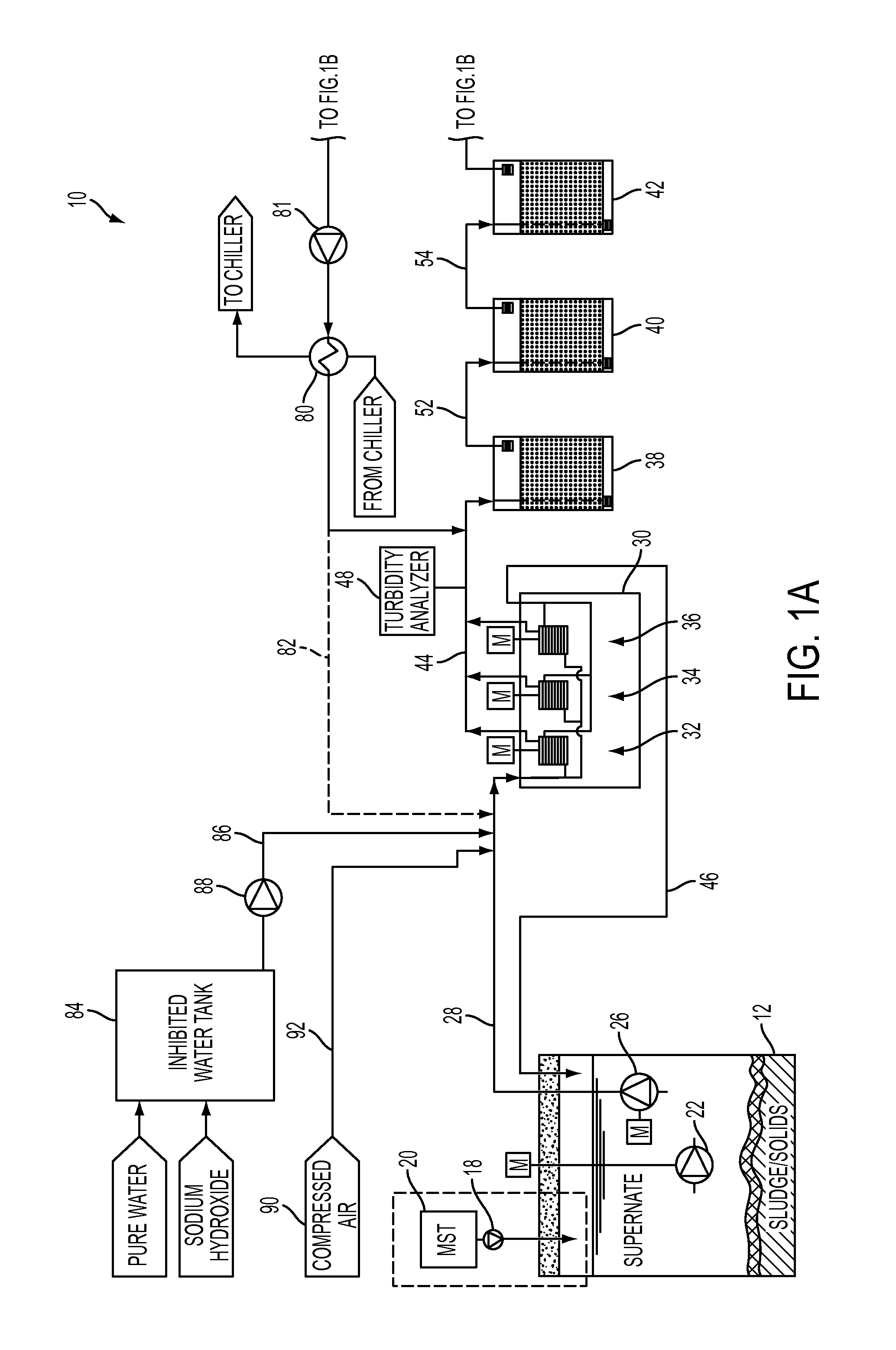
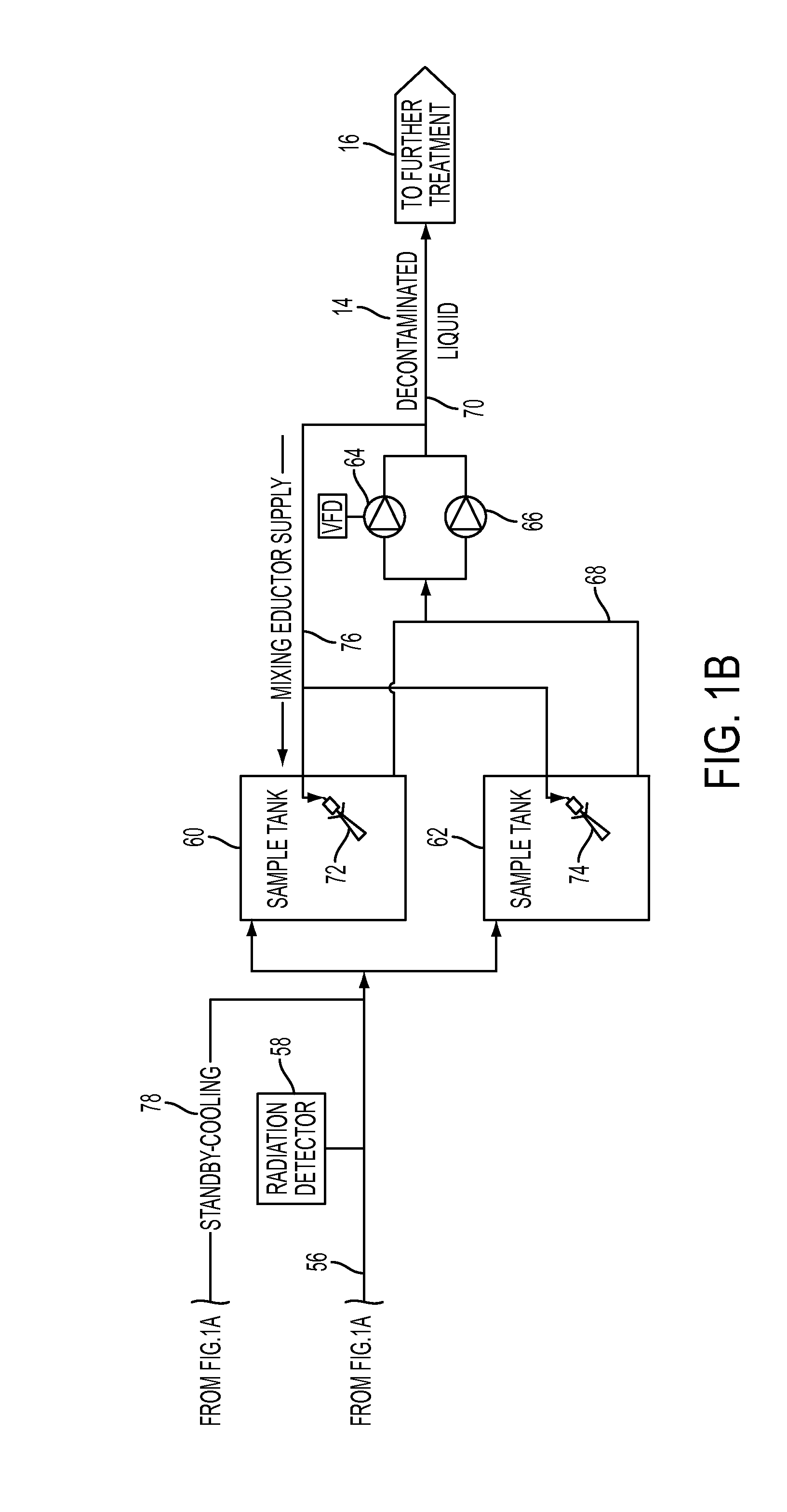
Apparatus and Method for Removal of Radionuclides in Liquids
a radionuclide and liquid technology, applied in the direction of radioactive contaminants, nuclear elements, separation processes, etc., can solve the problems of large, highly toxic quantities of high-level radioactive waste located on the srs and hanford sites, waste will still be radioactive, and no longer mobile
- Summary
- Abstract
- Description
- Claims
- Application Information
AI Technical Summary
Benefits of technology
Problems solved by technology
Method used
Image

Examples
Embodiment Construction
[0030]Reference will now be made in detail to presently preferred embodiments of the invention, one or more examples of which are illustrated in the accompanying drawings. Each example is provided by way of explanation of the invention, not limitation of the invention. In fact, it will be apparent to those skilled in the art that modifications and variations can be made in the present invention without departing from the scope or spirit thereof. For instance, features illustrated or described as part of one embodiment may be used on another embodiment to yield a still further embodiment. Thus, it is intended that the present invention covers such modifications and variations.
[0031]Various systems and techniques of liquid treatment for removal of radioactive material in the liquid are shown and described in U.S. Pat. No. 6,387,274, entitled “System and Method for the Removal of Radioactive Particulate from Liquid Waste”; U.S. patent application Ser. No. 13 / 862,009, entitled “Wastewat...
PUM
| Property | Measurement | Unit |
|---|---|---|
| Length | aaaaa | aaaaa |
| Thickness | aaaaa | aaaaa |
| Flow rate | aaaaa | aaaaa |
Abstract
Description
Claims
Application Information
 - R&D
- Intellectual Property
- Life Sciences
- Materials
- Tech Scout
- Unparalleled Data Quality
- Higher Quality Content
- 60% Fewer Hallucinations
Browse by: Latest US Patents, China's latest patents, Technical Efficacy Thesaurus, Application Domain, Technology Topic, Popular Technical Reports.
© 2025 PatSnap. All rights reserved.Legal|Privacy policy|Modern Slavery Act Transparency Statement|Sitemap|About US| Contact US: help@patsnap.com