
Zinc Ion-Exchanging Energy Storage Device

Active Publication Date: 2016-10-13
GLOBAL GRAPHENE GRP INC
View PDF5 Cites 120 Cited by
  • Summary
  • Abstract
  • Description
  • Claims
  • Application Information

AI Technical Summary

Benefits of technology

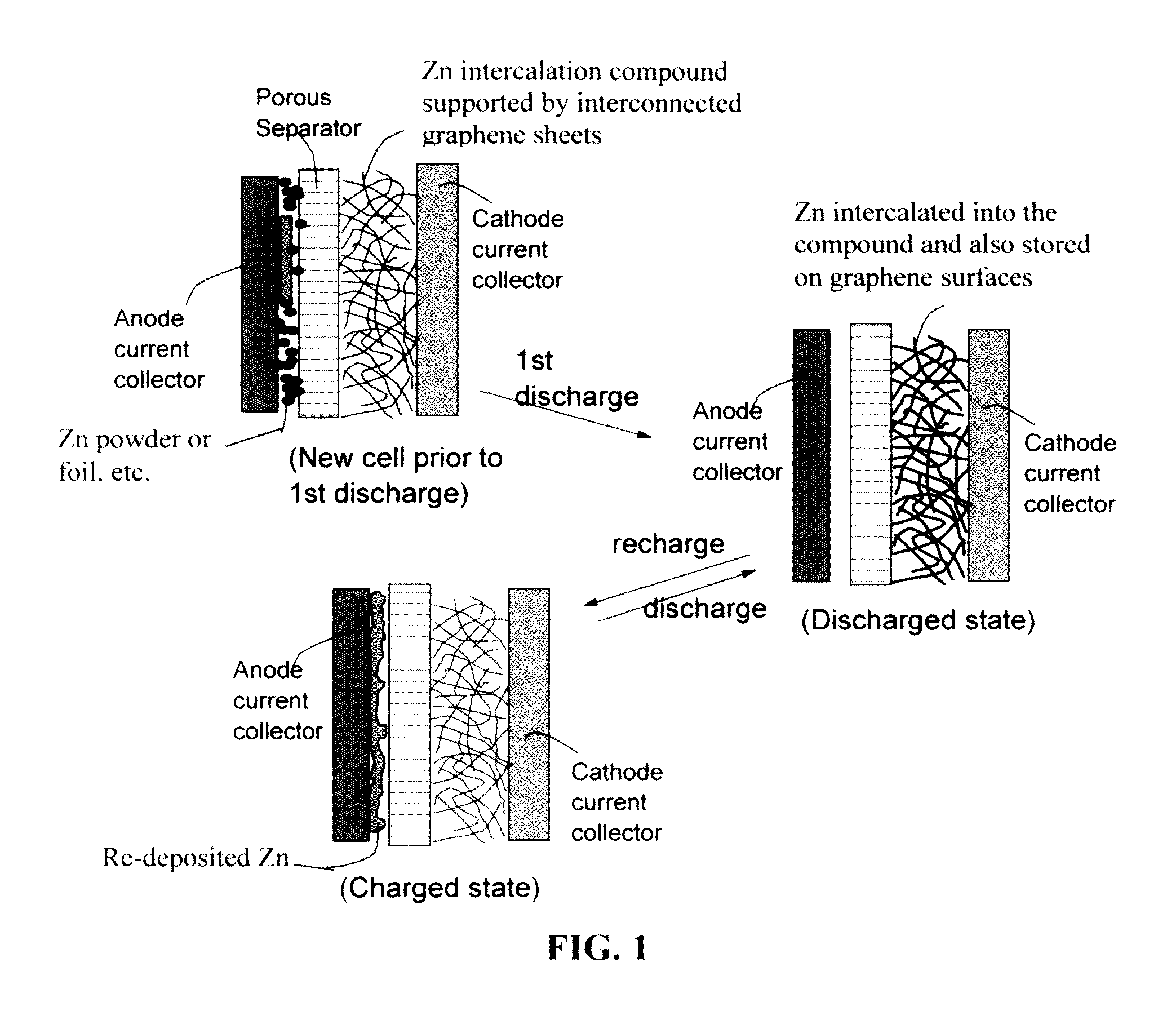
The patent describes a new type of material that can be used in batteries to improve their performance. This material contains a compound called MnO2, which is made by intercalating zinc ions into a surface-mediating material like exfoliated graphite or chemically functionalized graphene. By using these specific materials, the resulting battery has faster charging and discharging rates, high power density, and is more efficient. The patent also suggests that anode current collectors with a specific surface area should be used to ensure quick release of zinc ions during battery discharge and deposition during battery charge.

Problems solved by technology

However, supercapacitors, albeit delivering a high power density (e.g. up to 8 kW / kg), are incapable of storing a high amount of energy per unit cell weight (e.g. typically, 5-8 Wh / kg vs.
Although capable of storing a much higher energy density than a supercapacitor, lithium-ion batteries deliver a very low power density (typically 100-500 W / Kg based on total cell weight), requiring typically hours for re-charge.
Conventional lithium-ion batteries also pose some safety concern.
These intercalation or diffusion processes require a long time to accomplish because solid-state diffusion (diffusion inside a solid) is difficult and slow.
However, the cycle life of alkaline manganese dioxide rechargeable batteries has been limited to typically 20-30 cycles due to irreversibility associated with MnO2 upon deep discharge and formation of electrochemically inactive phases.
The Zn anode also has limitations on cycle life due to the redistribution of Zn active material and formation of dendrites during recharge, causing short-circuits.
However, long-term cycling stability and power density issues remain to be resolved.
Due to these reasons, the commercialization of this battery has been limited.

Method used


Image

  • Zinc Ion-Exchanging Energy Storage Device
  • Zinc Ion-Exchanging Energy Storage Device
  • Zinc Ion-Exchanging Energy Storage Device

Examples


example 1

Preparation of Graphene Oxide (GO) and Reduced Graphene Oxide (RGO) Nano Sheets from Natural Graphite Powder and their Paper / Mats (Layers of Porous Structure)

[0130]Natural graphite from Huadong Graphite Co. (Qingdao, China) was used as the starting material. GO was obtained by following the well-known modified Hummers method, which involved two oxidation stages. In a typical procedure, the first oxidation was achieved in the following conditions: 1100 mg of graphite was placed in a 1000 mL boiling flask. Then, 20 g of K2S2O8, 20 g of P2O5, and 400 mL of a concentrated aqueous solution of H2SO4 (96%) were added in the flask. The mixture was heated under reflux for 6 hours and then let without disturbing for 20 hours at room temperature. Oxidized graphite was filtered and rinsed with abundant distilled water until neutral pH. A wet cake-like material was recovered at the end of this first oxidation.

[0131]For the second oxidation process, the previously collected wet cake was placed in...

example 2

Preparation of Discrete Functionalized GO Sheets from Graphite Fibers and Porous Films of Chemically Functionalized GO

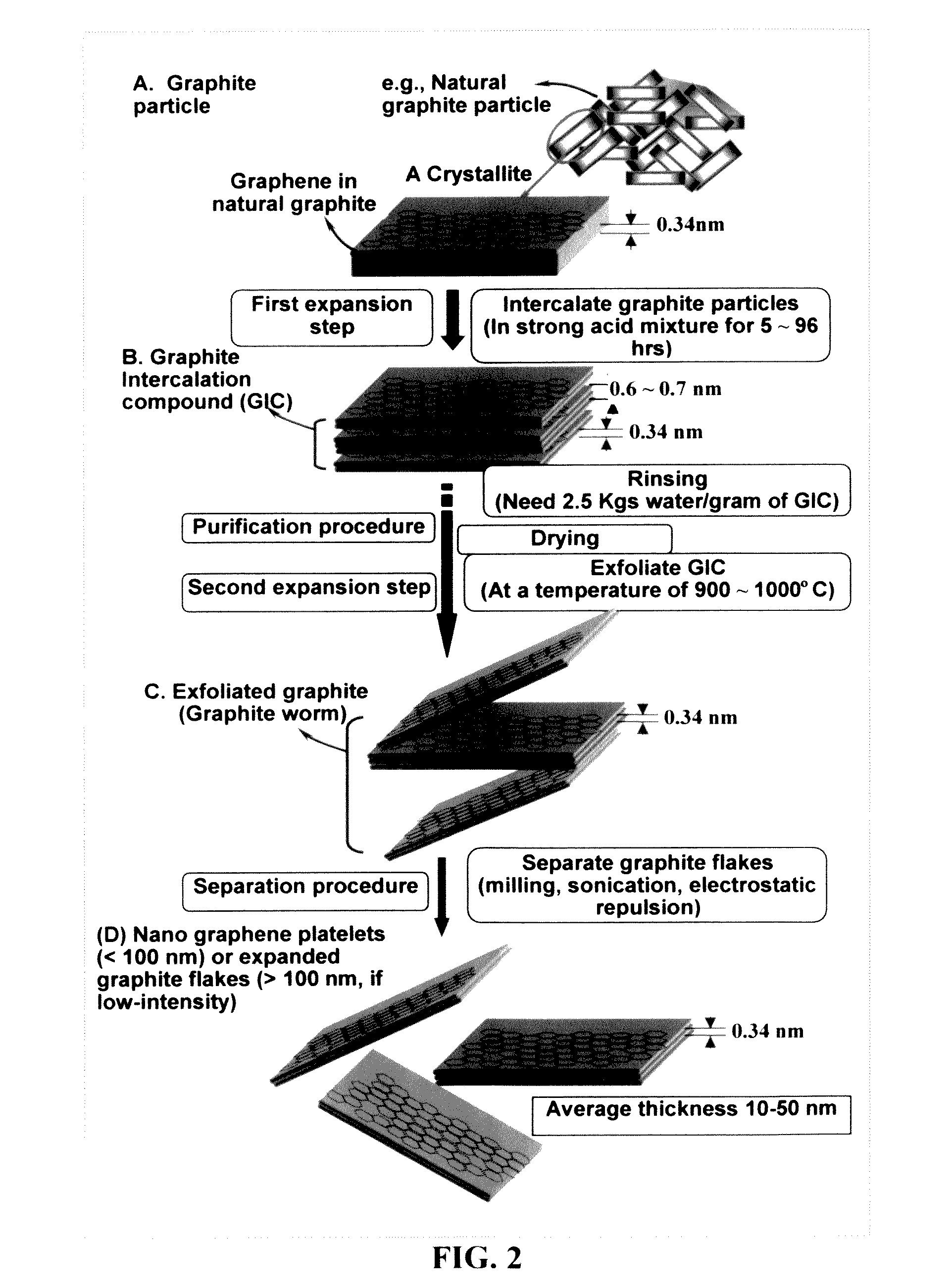
[0134]Chopped graphite fibers with an average diameter of 12 μm and natural graphite particles were separately used as a starting material, which was immersed in a mixture of concentrated sulfuric acid, nitric acid, and potassium permanganate (as the chemical intercalate and oxidizer) to prepare graphite intercalation compounds (GICs). The starting material was first dried in a vacuum oven for 24 h at 80° C. Then, a mixture of concentrated sulfuric acid, fuming nitric acid, and potassium permanganate (at a weight ratio of 4:1:0.05) was slowly added, under appropriate cooling and stirring, to a three-neck flask containing fiber segments. After 5-16 hours of reaction, the acid-treated graphite fibers or natural graphite particles were filtered and washed thoroughly with deionized water until the pH level of the solution reached 6. After being dried at 100° C. overnight...

example 3

Preparation of Single-Layer Graphene Sheets and Porous Graphene Mats from Meso-Carbon Micro-Beads (MCMBs)

[0137]Meso-carbon micro-beads (MCMBs) were supplied from China Steel Chemical Co., Kaohsiung, Taiwan. This material has a density of about 2.24 g / cm3 with a median particle size of about 16 μm. In one example, MCMB (10 grams) were intercalated with an acid solution (sulfuric acid, nitric acid, and potassium permanganate at a ratio of 4:1:0.05) for 48-96 hours. Upon completion of the reaction, the mixture was poured into deionized water and filtered. The intercalated MCMBs were repeatedly washed in a 5% solution of HCl to remove most of the sulphate ions. The sample was then washed repeatedly with deionized water until the pH of the filtrate was no less than 4.5. The slurry was then subjected ultrasonication for 10-100 minutes to fully exfoliate and separate GO sheets. TEM and atomic force microscopic studies indicate that most of the GO sheets were single-layer graphene when the ...


PUM


Abstract

A zinc ion-exchanging battery device comprising: (A) a cathode comprising two cathode active materials (a zinc ion intercalation compound and a surface-mediating material); (B) an anode containing zinc metal or zinc alloy; (C) a porous separator disposed between the cathode and the anode; and (D) an electrolyte containing zinc ions that are exchanged between the cathode and the anode during battery charge / discharge. The zinc ion intercalation compound is selected from chemically treated carbon or graphite material having an expanded inter-graphene spacing d002 of at least 0.5 nm, or an oxide, carbide, dichalcogenide, trichalcogenide, sulfide, selenide, or telluride of niobium, zirconium, molybdenum, hafnium, tantalum, tungsten, titanium, vanadium, chromium, cobalt, manganese, iron, nickel, or a combination thereof. The surface-mediating material contains exfoliated graphite or multiple single-layer sheets or multi-layer platelets of a graphene material.

Description

FIELD OF THE INVENTION[0001]The present invention is directed at a new type of energy storage device, herein referred to as the zinc ion-exchanging battery device wherein the operation of the cathode depends upon a combination of both zinc ion intercalation (i.e. zinc ion diffusion in and out of the bulk of a solid electrode-active material) and zinc ion surface storage (“surface-mediated” or “surface-enabled”). This device has exceptionally high energy density and power density.BACKGROUND OF THE INVENTION[0002]Supercapacitors and lithium-ion batteries are two promising energy storage devices for electric vehicle applications. However, supercapacitors, albeit delivering a high power density (e.g. up to 8 kW / kg), are incapable of storing a high amount of energy per unit cell weight (e.g. typically, 5-8 Wh / kg vs. 150-200 Wh / kg of lithium-ion batteries).[0003]Although capable of storing a much higher energy density than a supercapacitor, lithium-ion batteries deliver a very low power d...

Claims


Application Information

Patent Timeline
IPC IPC(8): H01M10/054H01M4/583H01M4/48H01M4/58H01M4/485H01M4/80H01M4/52H01M10/0568H01M10/26H01M10/0569H01M4/70H01M4/66H01M10/056H01M4/50
CPCH01M10/054H01M2220/20H01M4/583H01M4/48H01M4/58H01M4/485H01M4/50H01M4/52H01M10/0568H01M10/26H01M10/0569H01M4/70H01M4/663H01M4/806H01M4/808H01M2300/0014H01M2300/0028H01M2300/0037H01M10/056H01G11/02H01G11/04H01G11/24H01G11/30H01G11/36H01G11/60H01G11/62H01M4/38H01M4/42H01M4/502H01M4/505H01M2300/0002H01M2300/0045Y02E60/10Y02T10/70
Inventor ZHAMU, ARUNAJANG, BOR Z.
Owner GLOBAL GRAPHENE GRP INC
Learn More