
Electrical current generation system

a technology of electric current and fuel cell, which is applied in the direction of electrochemical generators, energy input, separation processes, etc., can solve the problems of limited widespread use of fuel cells as power generation systems, severe impairment of pem fuel cells performance, and inability to meet the needs of large fuel cell siz

Inactive Publication Date: 2005-07-26
AIR PROD & CHEM INC
View PDF191 Cites 115 Cited by
  • Summary
  • Abstract
  • Description
  • Claims
  • Application Information

AI Technical Summary

Benefits of technology

[0021]In another variation, restrictor orifices are disposed between the light reflux exit compartment and the light reflux return compartment for pressure letdown in replacement of the light reflux expander. The gas recirculating means comprises a compressor coupled to the cathode gas outlet for supplying oxygen gas to the cathode gas inlet, and a restrictive orifice disposed between the cathode gas outlet and a pressurization compartment for recycling a portion of the oxygen gas as feed gas to the pressure swing adsorption system. As a result, energy recovered from the cathode gas outlet can be used to help pressurize the cathode gas inlet through the PSA system.
[0022]The electrical current generating system, according to a second embodiment of the present invention, comprises a fuel cell, an oxygen gas delivery system, and a hydrogen gas delivery system. The fuel cell includes an anode channel having an anode gas inlet and an anode gas outlet, a cathode channel having a cathode gas inlet and a cathode gas outlet, and an electrolyte in communication with the anode and cathode channel for facilitating ion exchange between the anode and cathode channel.

Problems solved by technology

However, several factors have limited the widespread use of fuel cells as power generation systems.
However, with atmospheric air as the direct source of oxygen to the cathode channel, performance of PEM fuel cells is severely impaired by the low partial pressure of oxygen and the concentration polarization of nitrogen, while alkaline fuel cells require a pretreatment purification system to remove carbon dioxide from the feed air.
Further, as the average oxygen concentration in a cathode channel with atmospheric air feed is typically only about 15%, the size of the fuel cell must be undesirably large in order to provide sufficient power for industrial applications.
As will be appreciated, the power input necessary to sufficiently compress the air feed reduces the overall efficiency of the fuel cell system.
It has been proposed to use polymeric membranes to enrich the oxygen, but such membranes actually reduce the oxygen partial pressure and the reduction in total pressure more than offsets the limited enrichment attainable.
External production, purification, dispensing and storage of hydrogen (either as compressed gas or cryogenic liquid) requires costly infrastructure, while storage of hydrogen fuel on vehicles presents considerable technical and economic barriers.
However, the resulting hydrogen contains carbon monoxide and carbon dioxide impurities which cannot be tolerated respectively by the PEM fuel cell catalytic electrodes and the alkaline fuel cell electrolyte in more than trace levels.
This results in a large load of nitrogen having to be heated and then cooled through the fuel processor system.
The substantial volume of nitrogen contributes to pressure losses throughout the fuel processor and anode channels, or alternatively to the cost and physical bulk penalties of making those passages larger.
While water recovery from fuel cell exhaust is highly desirable for efficient fuel processor operation, the conventional fuel cell discharges its oxygen-depleted cathode exhaust gas to atmosphere, and thus requires an extra condenser to recover water which then must be vaporized in the fuel processor at a substantial energy cost.
This condenser adds to the radiator cooling load which is already a problem for automotive fuel cell power plants in view of the large amount of low grade heat which must be rejected.
The conventional method of removing residual carbon monoxide from the hydrogen feed to PEM fuel cells has been catalytic selective oxidation, which compromises efficiency as both the carbon monoxide and a fraction of the hydrogen are consumed by low temperature oxidation, without any recovery of the heat of combustion.
Palladium diffusion membranes can be used for hydrogen purification, but have the disadvantages of delivery of the purified hydrogen at low pressure, and also the use of rare and costly materials.
This system is often difficult and expensive to implement due to the complexity of the valving required.
Further, the conventional PSA system makes inefficient use of applied energy, because feed gas pressurization is provided by a compressor whose delivery pressure is the highest pressure of the cycle.
These energy sinks reduce the overall efficiency of the fuel cell system.
Additionally, conventional PSA systems can generally only operate at relatively low cycle frequencies, necessitating the use of large adsorbent inventories.
The consequent large size and weight of such PSA systems renders them unsuitable for vehicular fuel cell applications.

Method used


Image

  • Electrical current generation system
  • Electrical current generation system
  • Electrical current generation system

Examples


first embodiment

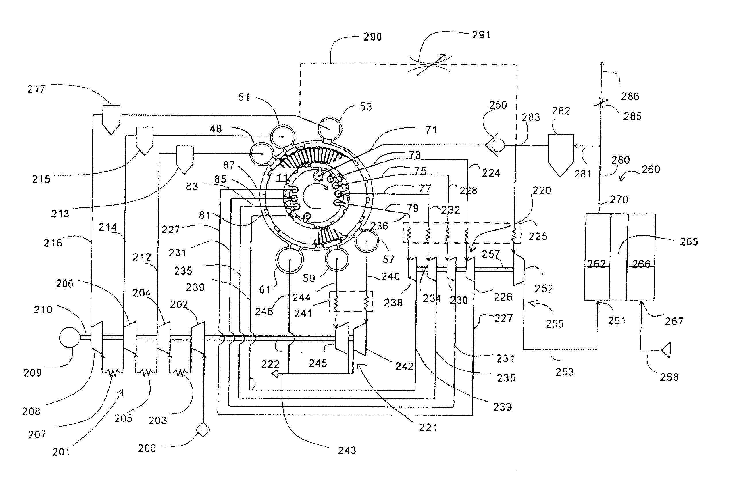
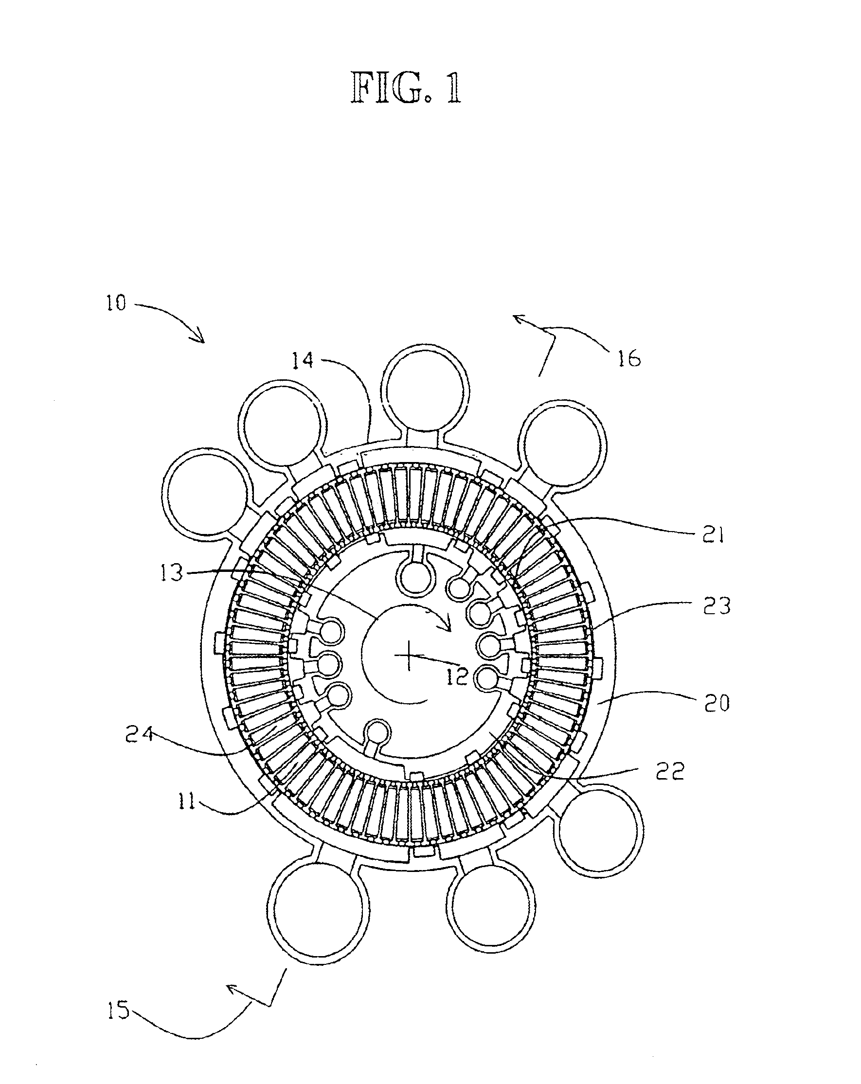
[0089]Turning now to FIGS. 9 and 10, fuel cell-based electrical current generating systems, according to the present invention, are shown using a rotary PSA system similar to that shown in FIG. 7 as the basic building block. However, it should be understood that the invention is not limited to electrical current generating systems having rotary PSA modules. Rather other arrangements may be employed without departing from the scope of the invention.

[0090]In FIG. 9, the PSA system separates oxygen from air, using nitrogen-selective zeolite adsorbents, as previously described. The light product is concentrated oxygen, while the heavy product is nitrogen-enriched air usually vented as waste. The cycle lower pressure 152 is nominally atmospheric pressure, unless an optional vacuum pump is provided as in FIG. 8. Feed air is introduced through filter intake 200 to a feed compressor 201. The feed compressor includes compressor first stage 202, compressor second stage 204, compressor third s...

second embodiment

[0112]FIG. 12 shows a fuel-cell based electrical current generating system 400, according to the present invention, comprising a fuel cell 402, an oxygen-generating PSA system 404, and a hydrogen gas production system 406. The fuel cell comprises an anode channel 408 including an anode gas inlet 410 and an anode gas outlet 412, a cathode channel 414 including a cathode gas inlet 416 and a cathode gas outlet 418, and a PEM 420 in communication with the anode channel 408 and the cathode channel 414 for facilitating ion exchange between the anode channel 408 and the cathode channel 414.

[0113]The oxygen-PSA system 404 extracts oxygen gas from feed air, and comprises a rotary module 10, and a compressor 422 for delivering pressurized feed air to the feed compartments 424 of the rotary module 10. Preferably, the oxygen-PSA system 404 includes a vacuum pump 426 (or alternatively countercurrent blowdown expander) coupled to the compressor 422 for withdrawing nitrogen-enriched gas as heavy p...

embodiment 600

[0132]Embodiment 600 illustrates further aspects of the invention. For alkaline fuel cells, the crucial problem is removal of CO2 from both feed oxidant and hydrogen streams. The oxygen-PSA and hydrogen-PSA systems of this invention as described above will remove CO2 very effectively, since CO2 is much more strongly adsorbed than other permanent gas impurities. Oxygen enrichment is beneficial for all types of fuel cells in increasing voltage efficiency, although not usually justified except at high current densities. Alkaline fuel cells can use an under-sized oxygen-PSA for very effective carbon dioxide removal along with modest oxygen enrichment, or may use the same PSA device with an adsorbent lacking nitrogen / oxygen selectivity (e.g. activated carbon, or high silica zeolites) for carbon dioxide clean-up without oxygen enrichment. The rotary PSA module and compression machinery of this invention for entirely suitable for this role.

[0133]Alkaline fuel cells operating on ambient air...


PUM

PropertyMeasurementUnit
Pressureaaaaaaaaaa

Abstract

An electrical generating system consists of a fuel cell, and an oxygen gas delivery. The fuel cell includes and anode channel having an anode gas inlet for receiving a supply of hydrogen gas, a cathode channel having a cathode gas inlet and a cathode gas outlet, and an electrolyte in communication with the anode and cathode channel for facilitating ion exchange between the anode and cathode channel. The oxygen gas delivery system is coupled to the cathode gas inlet and delivers oxygen gas to the cathode channel. The electrical current generating system also includes gas recirculation means couple to the cathode gas outlet for recirculating a portion of cathode exhaust gas exhausted from the cathode gas outlet to the cathode gas inlet.

Description

CROSS REFERENCE TO RELATED APPLICATIONS[0001]The present application is a continuation-in-part of prior international application No. PCT / CA99 / 00823, filed Sep. 14, 1999, which claimed priority from U.S. provisional application No. 60 / 100,091, filed Sep. 14, 1998, and Canadian patent application No. 2,274,240, filed Jun. 10, 1999, which applications are incorporated herein by reference.FIELD[0002]The present invention relates to a fuel cell for the generation of electrical current. In particular, the present invention relates to a fuel cell-based electrical generation system which employs pressure swing adsorption for enhancing the efficiency of the fuel cell.BACKGROUND[0003]Fuel cells provide an environmentally friendly source of electrical current. One form of fuel cell used for generating electrical power includes an anode for receiving hydrogen gas, a cathode for receiving oxygen gas, and an alkaline electrolyte. Another form of fuel cell includes an anode channel for receiving ...

Claims


Application Information

Patent Timeline
IPC IPC(8): B01D53/047C01B3/00C01B3/48C01B13/02H01M8/04H01M8/06H01M8/10
CPCB01D53/047B01D53/0476B01D53/06C01B3/48C01B13/0259C01B13/027H01M8/04097H01M8/0662B01D53/053B01D53/261B01D2253/108B01D2256/12B01D2256/16B01D2257/102B01D2257/304B01D2257/406B01D2257/502B01D2257/504B01D2258/0208B01D2259/40001B01D2259/40005B01D2259/4068B01D2259/4566C01B2203/0244C01B2203/0283C01B2203/066C01B2203/0811C01B2203/0844C01B2203/142C01B2203/82C01B2210/0051H01M8/04022H01M8/04119H01M8/04156H01M8/0612H01M8/0625H01M2300/0082Y02C10/08Y02E60/50Y02P20/129Y02C20/40Y02P20/151
Inventor KEEFER, BOWIE G.MCLEAN, CHRISTOPHER R.BROWN, MICHAEL J.
Owner AIR PROD & CHEM INC
Learn More