Hidden Culling in Tile-Based Computer Generated Images

a computer generated image and hidden culling technology, applied in the field of hidden culling in tile-based computer generated graphics system, to achieve the effect of improving the effectiveness of depth culling, limiting the amount of memory space required, and improving any depth culling

Active Publication Date: 2014-09-18
IMAGINATION TECH LTD
View PDF6 Cites 26 Cited by
  • Summary
  • Abstract
  • Description
  • Claims
  • Application Information

AI Technical Summary

Benefits of technology

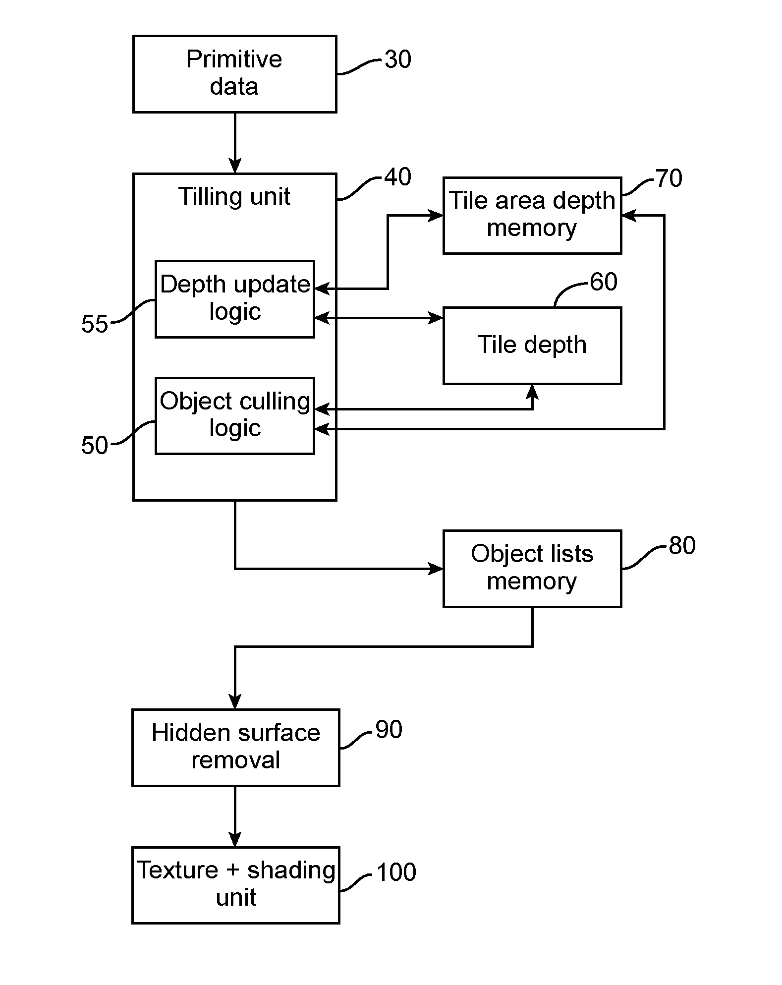
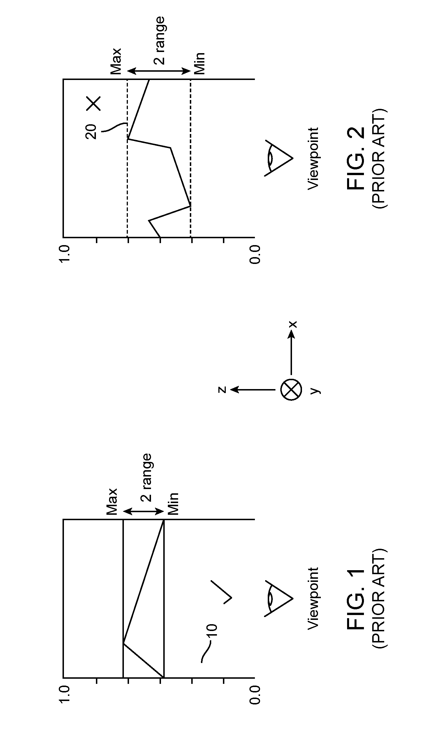
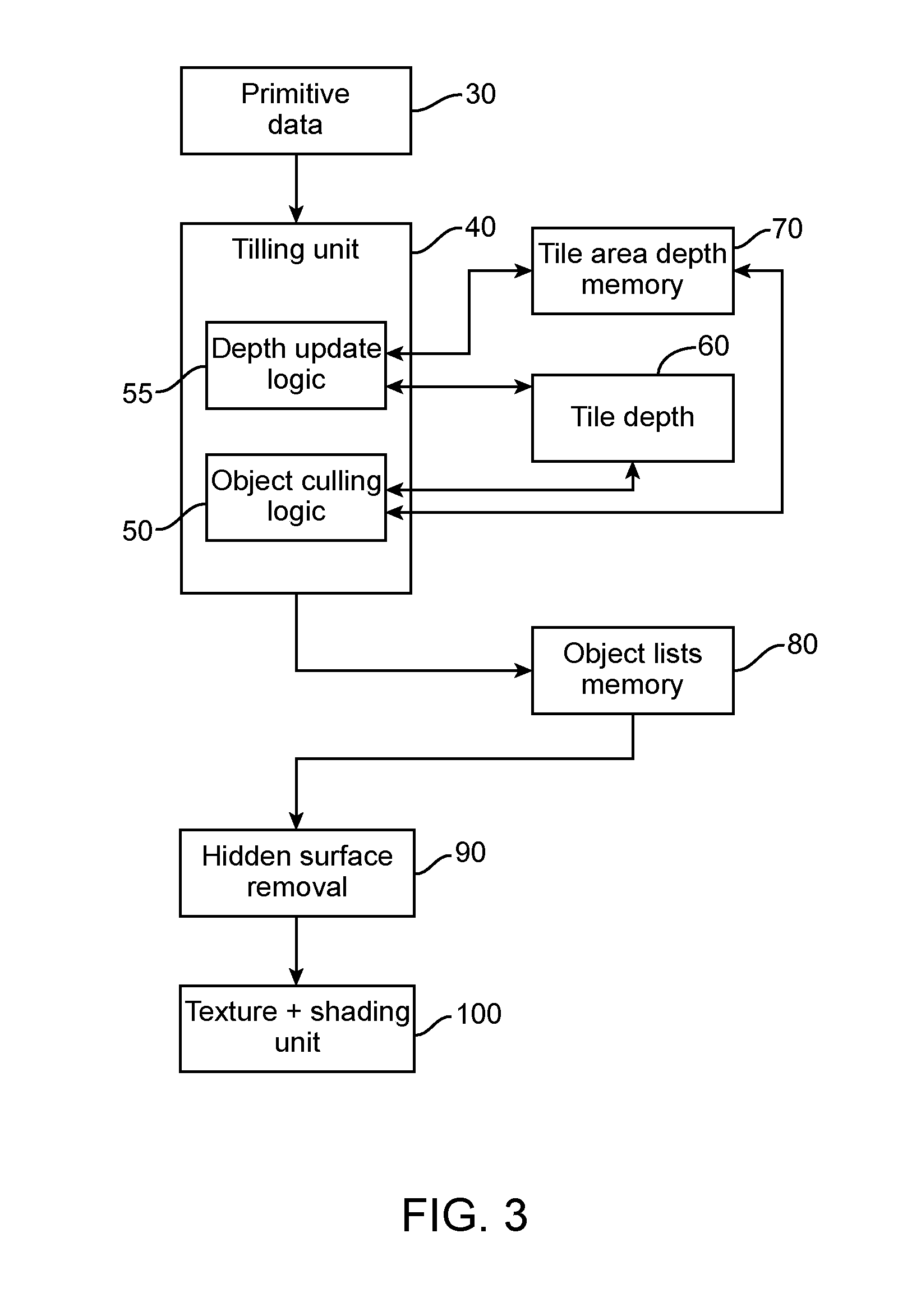
[0013]This method has the advantage that it can be used to cull non-visible or hidden objects in a tile-based graphics system before they are stored in a display list, without requiring the tile-based graphics system to perform “partial rendering”. It will be appreciated that the depth thresholds updated according to embodiments of the present invention are likely to be conservative values, since the depth thresholds are updated (so as to improve the depth cull) only when an object entirely covers a region. However, the applicant has appreciated that this method advantageously provides a relatively effective depth cull for a relatively small amount of processing power, which means that it is particularly suited for use during tiling where it is undesirable to repeat all of the processing which will be carried out by the renderer.
[0034]Where for example an object is located in a new tile, the depth thresholds for the areas of a tile presently in the memory device may be evicted from the memory device on a first in first out policy. However, more preferably, the depth thresholds for the areas are evicted from the memory device in dependence on how many of the depth thresholds for the areas have been updated and or on the difference between the depth thresholds for the areas. This reduces the amount of data which is lost when depth thresholds for the areas of a tile are evicted from the memory device.

Problems solved by technology

However, the applicant has appreciated that this method advantageously provides a relatively effective depth cull for a relatively small amount of processing power, which means that it is particularly suited for use during tiling where it is undesirable to repeat all of the processing which will be carried out by the renderer.

Method used


Image

  • Hidden Culling in Tile-Based Computer Generated Images
  • Hidden Culling in Tile-Based Computer Generated Images
  • Hidden Culling in Tile-Based Computer Generated Images

Examples


Embodiment Construction

[0049]The term “object” is used in the following to describe a graphical element such as a primitive or a model generally referred to within the computer graphics industry as a “patch” of surface data. A “patch” is typically a parametric function defined by a set of control points which describe the shape of a curve with respect to parameter “t” (for a curved line) or domain coordinates ‘u,v’ (for a curved surface). One example of a patch used in computer graphics is a Bezier patch, but others exist as will be appreciated by a person skilled in the art. Tessellation is a technique which involves breaking up a model or “patch” into a plurality of tessellated primitives. A patch is typically split into multiple primitives which may then be displaced by a function and / or in dependence on a displacement height map to create a plurality of tessellated primitives.

[0050]As will be known to those skilled in the art, tessellation of patches of surface data in a graphics pipeline can be suppo...


PUM


Abstract

A method and system is provided for culling hidden objects in a tile-based graphics system before they are indicated in a display list for a tile. A rendering space is divided into a plurality of regions which may for example be a plurality of tiles or a plurality of areas into which one or more tiles are divided. Depth thresholds for the regions, which are used to identify hidden objects for culling, are updated when an object entirely covers a region and in dependence on a comparison between a depth value for the object and the depth threshold for the region. For example, if the depth threshold is a maximum depth threshold, the depth threshold may be updated if an object entirely covers the tile and the maximum depth value of the object is less than the maximum depth threshold.

Description

FIELD OF INVENTION[0001]The present invention relates to a method and system for culling non-visible objects in a tile based computer generated graphics system.BACKGROUND TO THE INVENTION[0002]Tile based rendering is a known technique for rendering 2D or 3D computer graphics images. A rendering space is sub-divided into a plurality of regions called tiles or blocks, which are typically rectangular, and each comprises a plurality of pixels. The rendering space may correspond to an image for display on a screen, but other render targets, such as texture data in memory, are also possible. Tiles can be various sizes, but a typical size is for example 16×16 pixels. In a high screen resolution image there are typically 1280×1024 pixels. Therefore, a high screen resolution image may be sub-divided into 5120 tiles (each comprising 16×16 pixels).[0003]Primitive data representing geometrical objects is read from memory and transformed into screen space. Primitives are often polygons, typicall...

Claims


Application Information

Patent Timeline
Patent Type & Authority Applications(United States)
IPC IPC(8): G06T15/40
CPCG06T15/405G06T15/005G06T15/40
Inventor YANG, XILEHOWSON, JOHN W.FENNEY, SIMON
Owner IMAGINATION TECH LTD
Why Eureka
Try Eureka