2D/3D Localization and Pose Estimation of Harness Cables Using A Configurable Structure Representation for Robot Operations

a technology of structure representation and 2d/3d localization, applied in the field of robot recognition and manipulation of cable harnesses, can solve the problems of distortion, ineffective approach, and easy to see limitations of this approach

Active Publication Date: 2014-09-18
SEIKO EPSON CORP
View PDF6 Cites 106 Cited by
  • Summary
  • Abstract
  • Description
  • Claims
  • Application Information

AI Technical Summary

Benefits of technology

[0057]In this case, it is preferred that step (b) further include: identifying as a candidate matching descriptor, a feature descriptor in the second set that matches a given feature descriptor in the first set; and IF its relative position within the second image differs from the relative position of the given feature descriptor in the first image by more than a predefined margin, THEN discarding the candidate matching descriptor, ELSE deeming the candidate matching descriptor as a corresponding pixel pair to the given feature descriptor.

Problems solved by technology

For complex searches, however, this approach is not effective.
The limitations of this approach become readily apparent when the subject being sought within an image is not static, but is prone to change.
For example, a human face has definite characteristics, and its distortion is limited, but it still does not have an easily definable number of shapes and / or appearance it may adopt.
Other objects may be prone to far deformation than a human face.
For example, cable harnesses have definite characteristics, but may take many different shapes and arrangements due to their wiring lacking many, if any, rigid structure.
Although an exhaustive library of samples of a known rigid body may be compiled for identification purposes, it is self-evident that compiling an exhaustive library of human faces, or any non-rigid or amorphous object, and their many variations is a practical impossibility.
Model-based vision, however, has proven more difficult in interpreting images of non-rigid object having unknown variations, such as images of natural subjects, which tend to be complex and variable.
A problem is the variability of the subject being examined.
For example, if aligning the model face meant moving its left eye up one inch and moving its right eye down one inch, then the resultant aligned image would likely not be a human face, and thus such a deformation would typically not be permissible.
This approach, however, does not take into account changes in appearance, i.e., shadow, color, or texture variations for example.
Although AAM is a useful approach, implementation of AAM still poses several challenges.
If the subject category is prone to a wide range of changes, such as cable harness that can take any distortion when dropped onto an assembly line (such as a conveyor belt) or when picked up, the model may not be able to properly align itself to an input subject image with characteristics beyond the norm defined by the shape or appearance model.
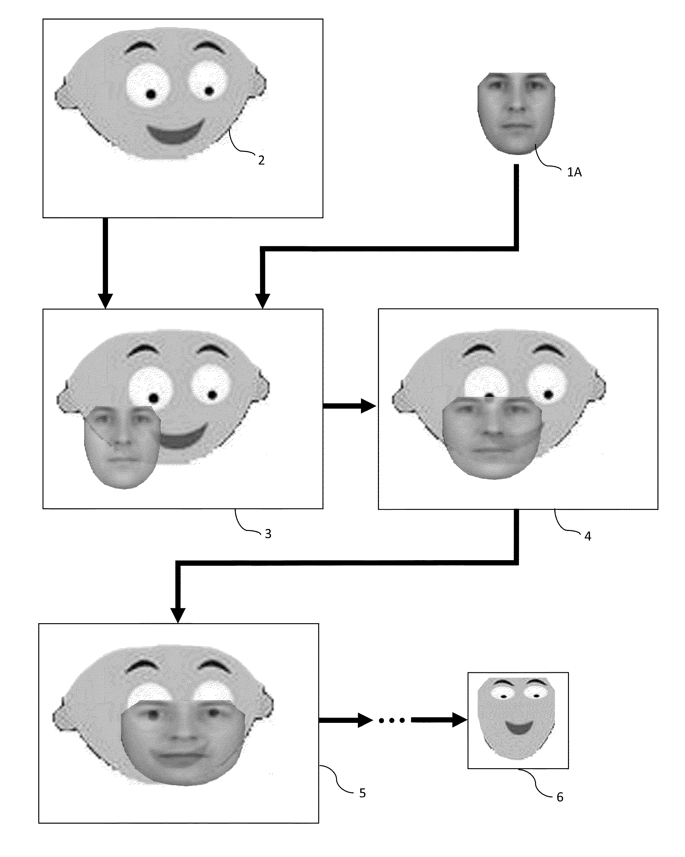
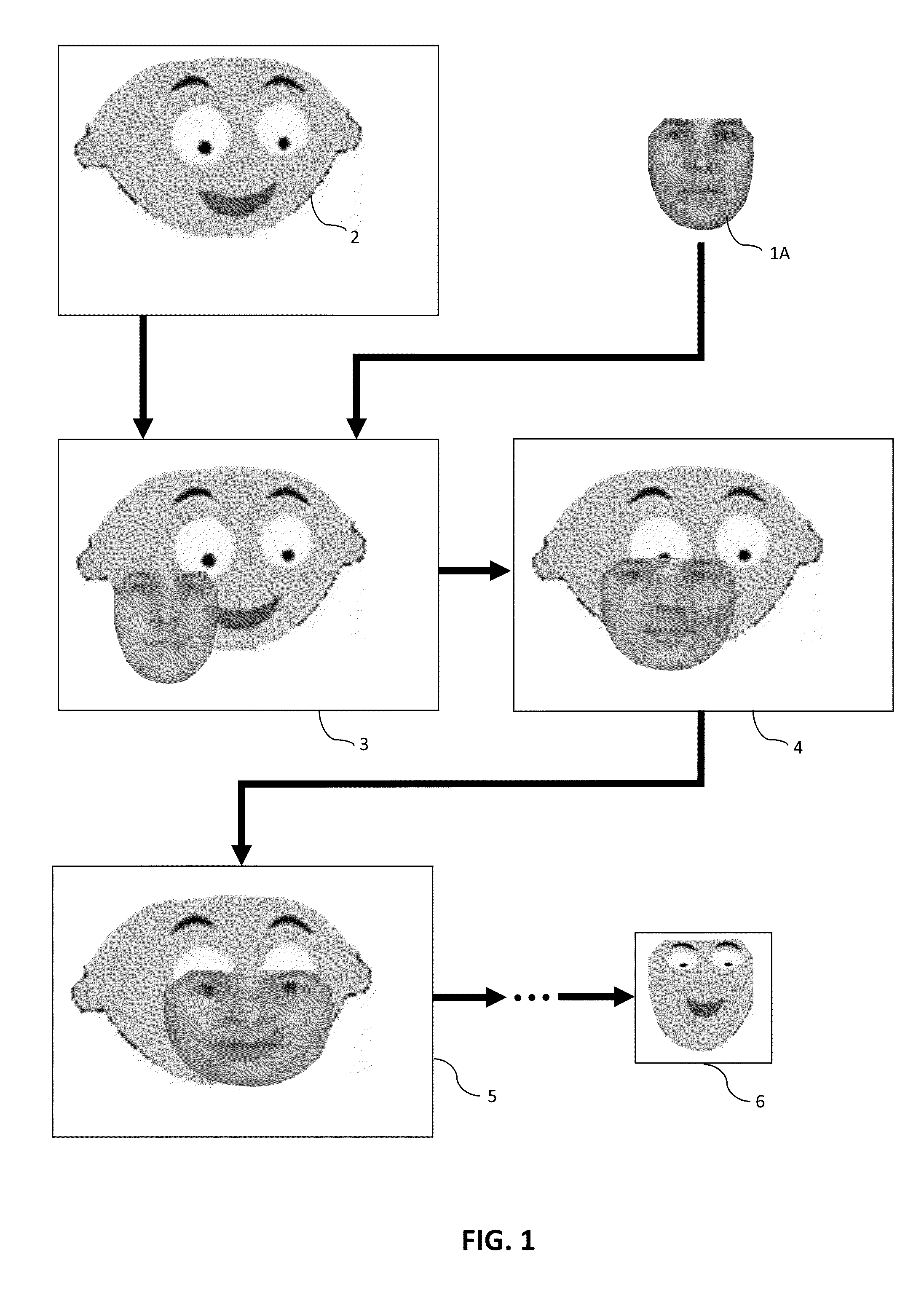
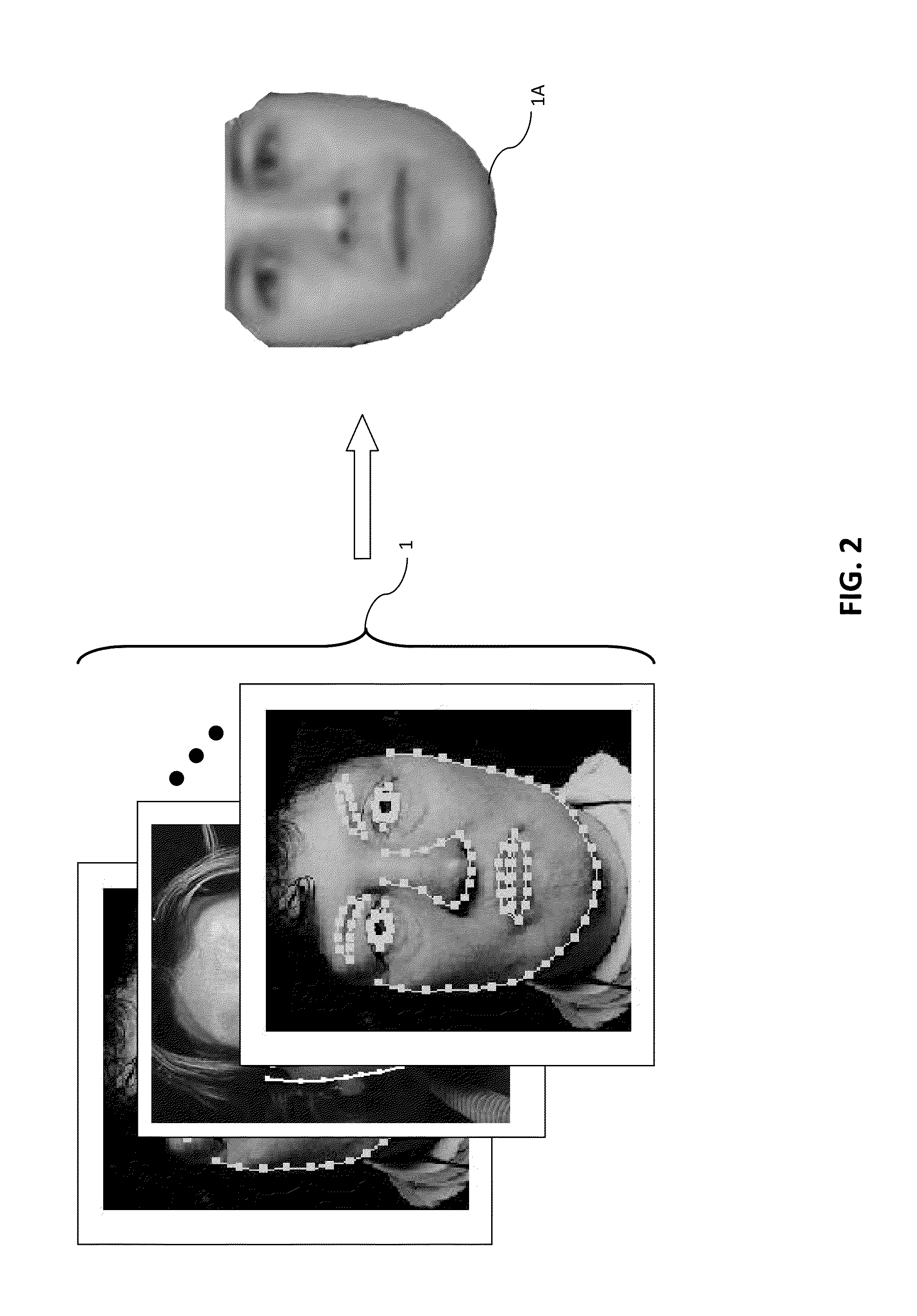
Another limitation of an AAM machine is that construction of the model (or conical) image (i.e., model face 1A in the example of FIG. 1) requires much human intervention to identify the distinguishing features of the specific object being sought.
Thus, an AAM machine may be too complicated and computationally intensive for practical machine vision applications in industrial assembly lines where the object class is prone to great deformation, such as when the object class is one or more types of wire harnesses.
Implementing such vision capabilities, however, is still a challenge, even in a specialized assembly line where the number of possible target object variants is limited.

Method used


Image

  • 2D/3D Localization and Pose Estimation of Harness Cables Using A Configurable Structure Representation for Robot Operations
  • 2D/3D Localization and Pose Estimation of Harness Cables Using A Configurable Structure Representation for Robot Operations
  • 2D/3D Localization and Pose Estimation of Harness Cables Using A Configurable Structure Representation for Robot Operations

Examples


Embodiment Construction

[0094]Automated assembly of components is critical to the manufacture of many items. Often, automated assembly is limited to relatively rigid components, or sub-components to facilitate the manipulation of the components. There is a need, however, for a robotic assembly to be able to manipulate non-rigid bodies. In particular, it would be beneficial for an automated system to be able to manipulate cable harness, which have a non-rigid structure and are prone to take many different configurations. It is further beneficial for such an automated system to be able to distinguish between different cable harnesses in a collection, and to be further able to identify specific parts of the cable harness. There is a further need for such an assembly to be able to discern the pose, i.e., orientation or arrangement, of cable harnesses in order identify specific connectors on the cable harnesses, and properly align a connector to a specific receptacle of the connector.

[0095]It is presently prefe...


PUM


Abstract

A robot is made to recognize and manipulate different types of cable harnesses in an assembly line. This is achieved by using a stereo camera system to define a 3D cloud of a given cable harness. Pose information of specific parts of the cable harness are determined from the 3D point cloud, and the cable harness is then re-presented as a collection of primitive geometric shapes of known dimensions, whose positions and orientations follow the spatial position of the represented cable harness. The robot can then manipulate the cable harness by using the simplified representation as a reference.

Description

BACKGROUND[0001]1. Field of Invention[0002]The present invention is generally directed to the field of robotic manipulation of objects. More specifically, it is directed towards robotic recognition and manipulation of cable harnesses.[0003]2. Description of Related Art[0004]In the field of automated, or robotic, manufacturing or assembly, the ability to identify assembly components, manipulate and attach them to other components is very important. Often, this is achieved by use of assembly stations, where each assembly station is limited to one component having one known orientation and requiring simplified manipulation.[0005]It would be advantageous, however, for a machine to be able to select a needed component from a supply of multiple components, identify any key assembly features of the component, and manipulate the selected component as needed for assembly. This would require that the machine have some capacity for computer vision, object recognition and manipulation.[0006]Bef...

Claims


Application Information

Patent Timeline
Patent Type & Authority Applications(United States)
IPC IPC(8): H04N13/02H04N13/239
CPCH04N13/0275G06T2207/10012G06T2207/10028G06T2207/30108G06T17/10G06T7/75G06T7/593G06T7/11G06T7/187H04N13/239H04N13/25H04N13/275G06V20/653G06V10/462G06V10/757G06V2201/06
Inventor DING, YUANYUANXIAO, JINGFUKASAWA, KENJI
Owner SEIKO EPSON CORP
Why Eureka
Try Eureka