

Precast concrete retaining wall
a technology of precast concrete and retaining walls, applied in the field of retaining walls, can solve the problems and achieve the effect of saving both installation and transportation costs and being easy to mak
- Summary
- Abstract
- Description
- Claims
- Application Information
AI Technical Summary
Benefits of technology
Problems solved by technology
Method used
Image

Examples
Embodiment Construction
[0034]While embodiments of this invention can take many different forms, specific embodiments thereof are shown in the drawings and will be described herein in detail with the understanding that the present disclosure is to be considered as an exemplification of the principles of the invention, and is not intended to limit the invention to the specific embodiment illustrated.
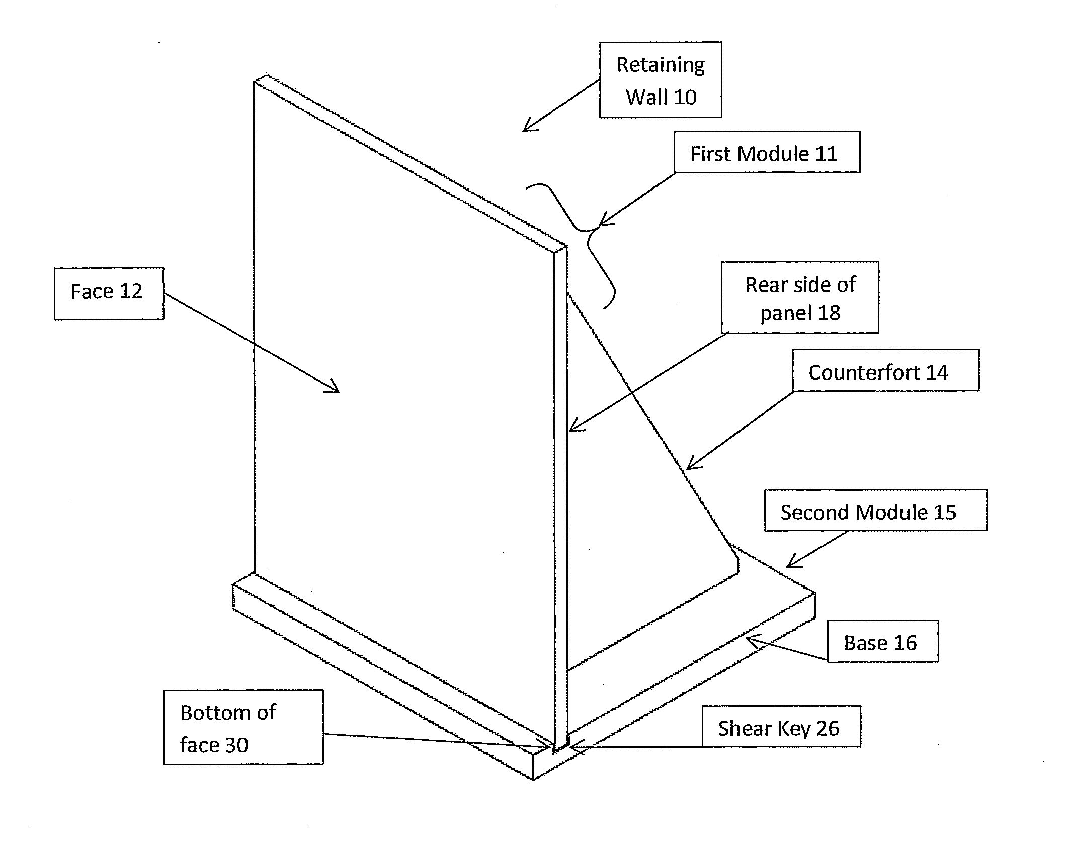
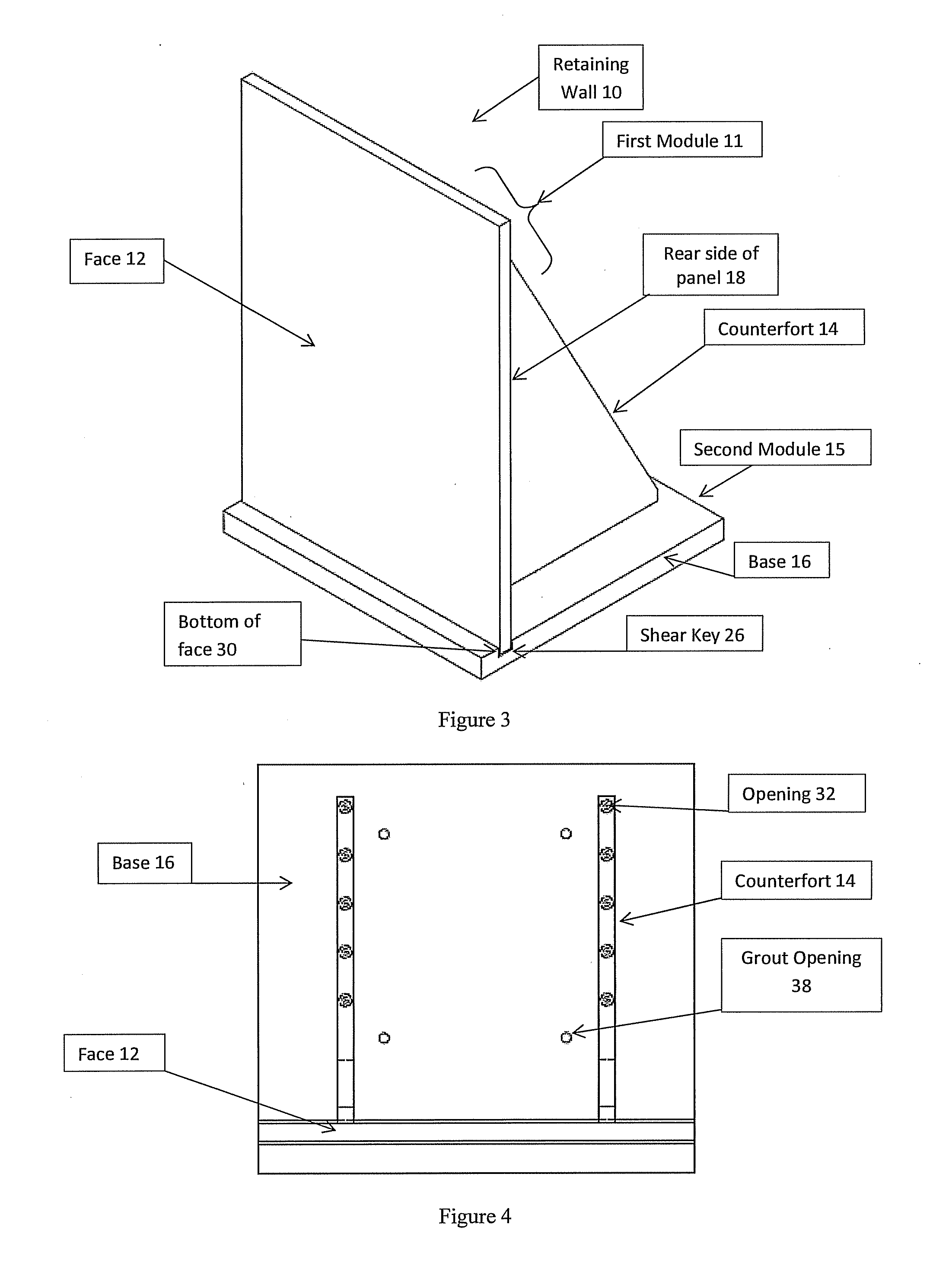
[0035]Referring to the drawings in detail, wherein like numerals indicate like elements throughout, there is shown in FIGS. 3-7 a preferred embodiment of a retaining wall in accordance with the various aspects of present invention. While retaining wall systems are commonly used in retaining soil, it should be understood that the present invention can be used in many different applications including retaining other materials such as sand, pebbles or rocks.
[0036]FIG. 3 illustrates a perspective view of an embodiment of wall 10 embodying principles of the present invention. The retaining wall 10 of the present inve...
PUM
 Abstract
Description
Claims
Application Information