
Gear-Driven Flow-Through Pitot Tube Pump

a pitot tube pump and gear drive technology, which is applied in the direction of radial flow pumps, non-positive displacement pumps, fluid engines with non-positive displacement, etc., can solve the problems of poor or inefficient balancing of the very heavy rotor, affecting the resistance ability, and limiting the sizing and design of the pump, so as to increase the sealing size, reduce the velocity characteristics, and increase the area

Active Publication Date: 2014-09-18
SPECIALTY PUMPS & SYST LLC
View PDF4 Cites 6 Cited by
  • Summary
  • Abstract
  • Description
  • Claims
  • Application Information

AI Technical Summary

Benefits of technology

The patent describes a pump assembly that includes a rotating assembly with a rotor and a rotating sleeve, a fluid inlet positioned to deliver fluid to the rotor, and a fluid discharge positioned axially spaced from the fluid inlet. This design increases the area of the rotor inlet compared to conventional pitot tube pumps without increasing the size of the seal, reducing velocity characteristics and improving the pump's performance. The pump also includes a centrifugal pump with a rotor and a fluid inlet / discharge that have increased areas, reducing velocity characteristics and improving the pump's performance. Additionally, the pump includes a seal housing to prevent fluid from entering the drive housing in the event of seal failure.

Problems solved by technology

Pitot tube pumps of this conventional construction can experience various disadvantages, including limitations on pump sizing and design to maximize pump efficiencies, poor or inefficient balancing of the very heavy rotor, bearing load designs that compromise the ability to resist the moment of an overhung rotor and seal leakage issues.
As a result of these limitations, pump efficiencies can be compromised and the life of the pump can be shortened.
However, these designs, due to the configuration of the pumps, result in high or significantly ineffective NPSH (net positive suction head).
They are also configured such that some of the pumps lack effective hydraulic axial thrust balance, and many of the pumps are unable to operate at high speeds or adequate pressures.
These prior known pumps can also be very complex and, therefore, costly to build and maintain, while also resulting in poor pump performance.
The leakage also increases the flow volume into the entrance to the rotor, thereby increasing the velocity and decreasing the NPSH performance.

Method used


Image

  • Gear-Driven Flow-Through Pitot Tube Pump
  • Gear-Driven Flow-Through Pitot Tube Pump
  • Gear-Driven Flow-Through Pitot Tube Pump

Examples


Embodiment Construction

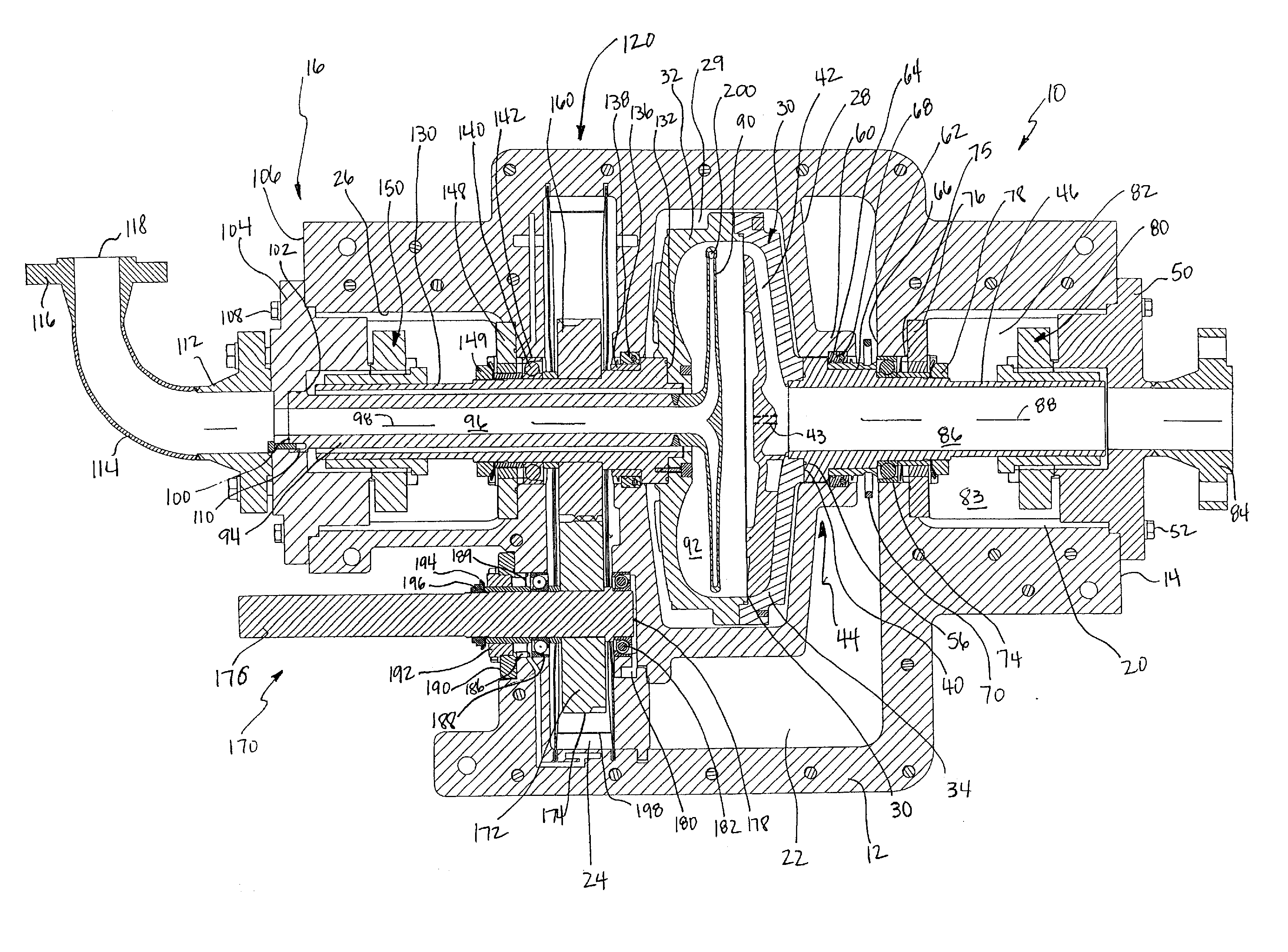
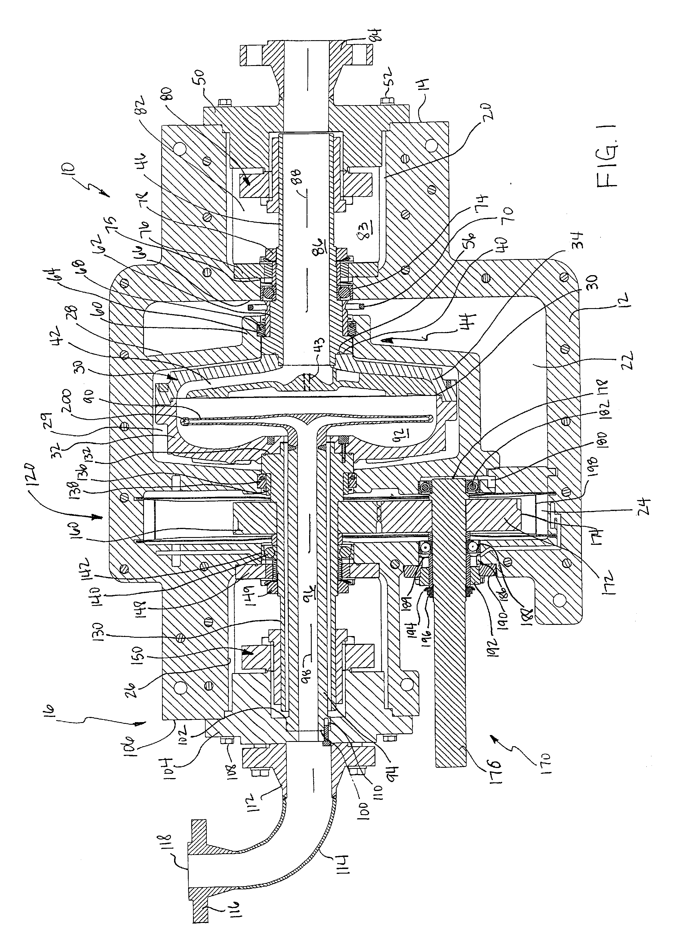
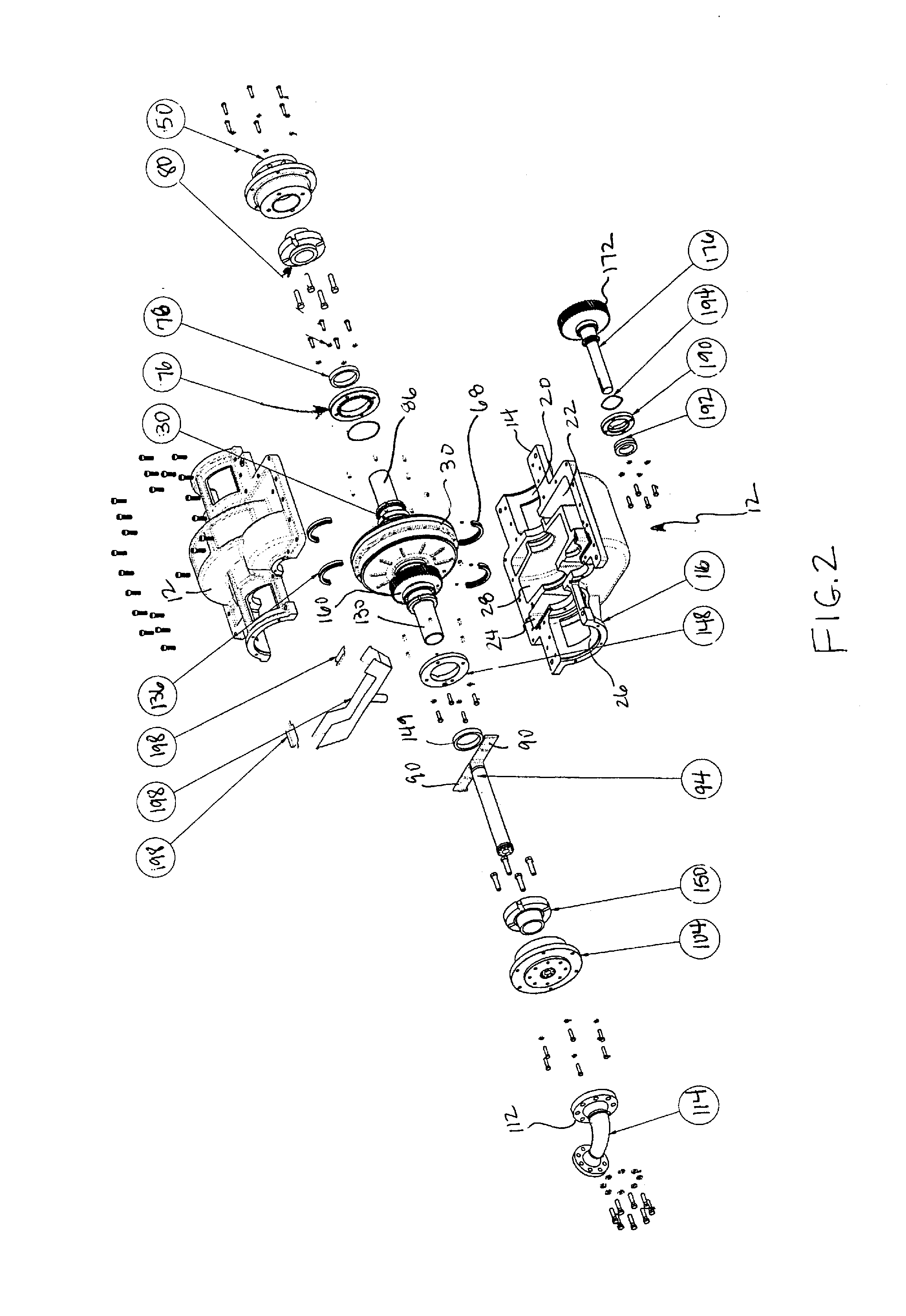
[0034]FIGS. 1 and 2 illustrate a first embodiment of a pitot tube assembly and pump 10 in accordance with the present disclosure. The pump 10 comprises a pump casing or pump housing 12 having a first end 14 and a second end 16, the two ends being in axially opposed orientation to each other. The pump housing 12 may be configured with a suction seal housing portion 20, a gear frame portion 22, a drive housing portion 24, a discharge housing portion 26 and a rotor housing portion 28.

[0035]The pump 10 is further comprised of a rotor 30 that is positioned in the rotor housing portion 28. The rotor housing portion 28 may be structured with a cavity 29 in which the rotor 30 is disposed. The rotor 30 has axially opposed sides that, in some embodiments, may be defined by a rotor bottom 32, comprising one side, and a rotor cover 34, comprising the opposing side that is axially spaced or axially positioned relative to the other side of the rotor 30. The rotor bottom 32 and rotor cover 34 are ...


PUM


Abstract

A centrifugal pump of the pitot type is structured with axially-arranged inlet and discharge features positioned on opposing axial sides of a rotor, the rotor being journalled between a rotating sleeve and a suction inlet, and the rotating sleeve being concentric with the discharge, the rotating sleeve being gear-driven by a drive mechanism.

Description

CROSS-REFERENCE TO RELATED APPLICATION[0001]This is a non-provisional application which claims priority to U.S. provisional application Ser. No. 61 / 798,539, filed Mar. 15, 2013, the contents of which are incorporated herein in full.TECHNICAL FIELD[0002]This disclosure relates in general to centrifugal pumps and, in particular, to an improved centrifugal pump of the pitot type having a flow-through, gear-driven configuration.BACKGROUND OF THE DISCLOSURE[0003]Centrifugal pumps are well known and widely used in a variety of industries to pump fluids or liquid / solid components of fluid mixtures. Centrifugal pumps, particularly those of the pitot type, generally comprise a pump housing having an inlet and an outlet and a rotor assembly which rotates within the pump housing by means of a drive unit. The fluid inlet and the fluid discharge in conventional pitot pumps are positioned in parallel orientation on the same side of the pump housing, in a side-by-side arrangement. Oftentimes, the ...

Claims


Application Information

Patent Timeline
Patent Type & Authority Applications(United States)
IPC IPC(8): F04D17/10
CPCF04D17/10F04D1/14F04D29/4293F04D1/12
Inventor NEILSON, BRYCE
Owner SPECIALTY PUMPS & SYST LLC
Features
  • Generate Ideas
  • Intellectual Property
  • Life Sciences
  • Materials
  • Tech Scout
  • Unparalleled Data Quality
  • Higher Quality Content
  • 60% Fewer Hallucinations
Learn More