Partially disposable endoscopic device

a technology of endoscope and endoscope, which is applied in the field of endoscope type instruments, can solve the problems of endoscope not being used, medical practitioners cannot advance the medical tool into the patient's body, etc., and achieve the effect of stable torsion

Inactive Publication Date: 2014-09-18
LUCENT MEDICAL SYST
View PDF27 Cites 109 Cited by
  • Summary
  • Abstract
  • Description
  • Claims
  • Application Information

AI Technical Summary

Benefits of technology

[0024]The endoscope 42 of FIG. 3 is representative of a conventional endoscope. In other conventional endoscopes, air, water, suction, and other therapeutic agents may be passed through different ports and controlled with different buttons than described herein. Additionally, the end assembly 80 may also be configured differently than what is illustrated. The endoscope 42 is not necessarily drawn to scale. Instead, the endoscope 42 of FIG. 3 is presented to illustrate particular structures and features common to many conventional endoscopes.
[0025]In accordance with some embodiments described herein, an endoscopic device has an image sensor arranged in a functional module at the steerable tip portion of a flexible tube attached to the endoscopic device. The tip can be steered in a back and forth direction of a common plane. The steering mechanism is configured for one-handed, either-handed use. The flexible tube is torque stable. As the flexible tube is rotate...

Problems solved by technology

In other traditional PEG tube placement procedures, endoscopy is not in the final step, or endoscopy may not be used...

Method used


Image

  • Partially disposable endoscopic device
  • Partially disposable endoscopic device
  • Partially disposable endoscopic device

Examples


embodiment 100

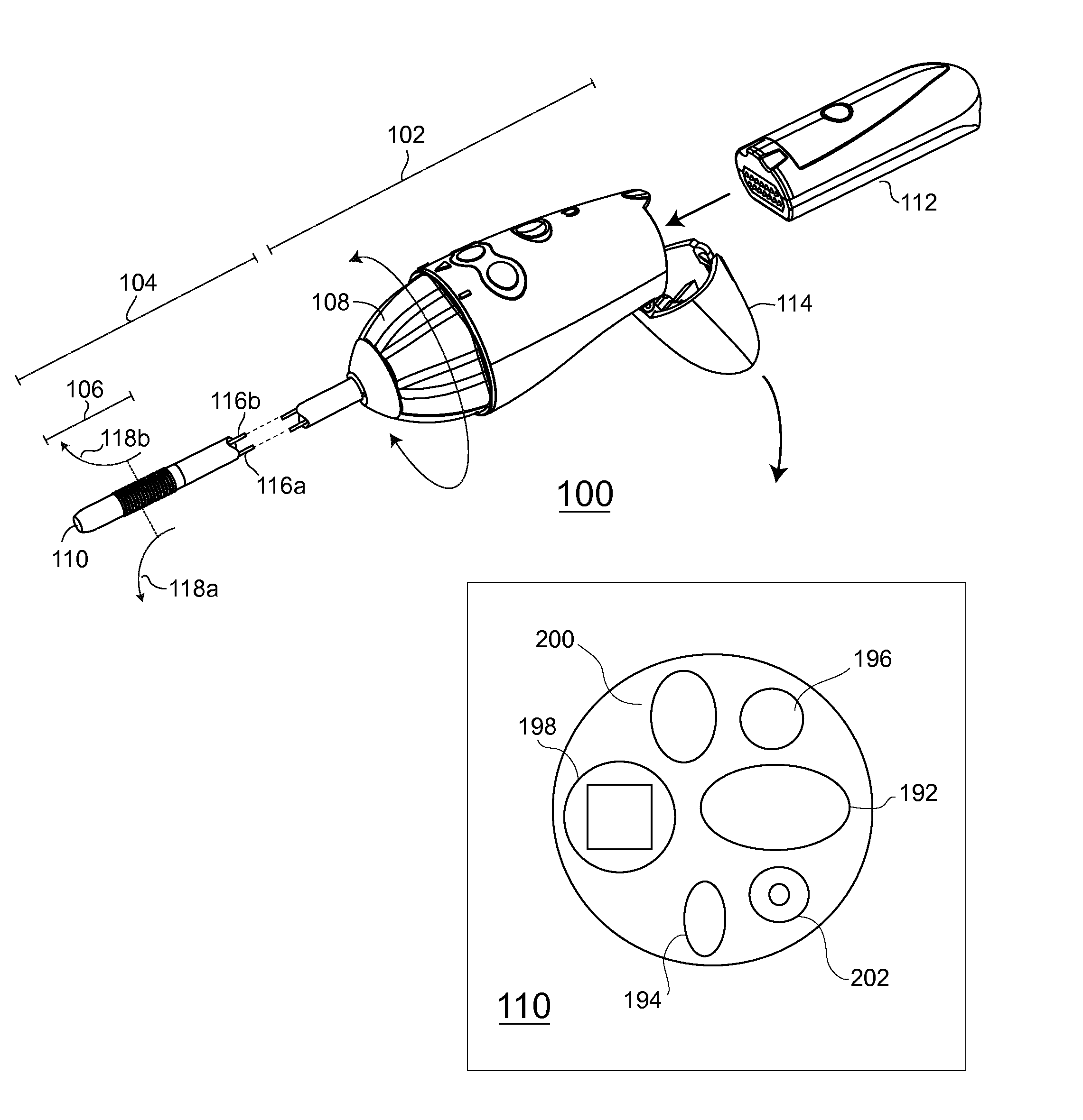
[0055]FIG. 4 is a perspective view of one embodiment of a partially disposable endoscopic device 100. The partially disposable endoscopic device 100 embodiment includes a disposable control handle shell (i.e., “handle body,”“handle portion,” etc.) 102 and a flexible tubular member (i.e., “tube body,”“flexible tube,” etc.) 104 coupled or coupleable to the handle body. A steerable tip portion 106 is integrated at a distal end of the tube body 104. The steerable tip 106 is controlled via symmetrical steering mechanism 108 integrated with the handle body 102. The endoscopic device embodiment 100 also includes a functional module 110 arranged at the steerable tip portion 106. The functional module 110 may include an image sensor module, a light source, nozzles, ports, apertures, and other functional features, which are later described in more detail. The functional module 110 is coupled to corresponding controls and structures located in the handle body 102. The functional module 110 may...

embodiment 108

[0099]FIG. 8 is an exploded view of a symmetrical steering mechanism embodiment 108 from a rear perspective. Steering cables 116a, 116b, which are arranged in a tube body 104 (not shown in FIG. 8), pass into the steering mechanism 108 via the outer and inner tube guide flanges 126, 128. The steering mechanism cover 124, which is sandwiched between the tube guide flanges 126, 128, includes a ring gear 138. A dashed-dotted line indicates the cooperative alignment of the ring gear 138 to a pinion gear 132 when the steering mechanism is assembled. Also upon assembly, the shaft of the pinion gear 132 is aligned and affixed in a steering cable drive pulley 140 (FIG. 9) mounted in a chassis 130. An optional encoder 152 is cooperatively coupled to the shaft of the pinion gear 132.

[0100]As illustrated in FIGS. 7A-7E and FIG. 8, the ring gear 138 is illustrated as forming a completely circular gear. Optionally, the ring gear may also be formed as a geared surface that is not circular. For exa...

embodiment 112

[0112]FIG. 13 is an overlay section view of the handle portion 102 of a partially disposable endoscopic device 100. The figure illustrates a control module embodiment 112 entering an exemplary recess formed in the disposable control handle shell 102. The surfaces of the control handle shell 102 are shown in dashed lines to better understand the illustration. In FIG. 13, hinged end cap 114 has been opened, and the control module 112 has been partially inserted into a recess in the control handle 102. A reference arrow shows the direction of insertion.

[0113]When the control module 112 is fully inserted into the recess in the control handle 102, the control module 112 will cooperatively mate with the steering cable drive pulley mounting chassis 130 enclosed and retained within the handle shell. Certain non-limiting structural features are shown on the steering cable drive pulley mounting chassis 130. Different structural features could also be used. FIG. 13 illustrates by way of an ast...


PUM


Abstract

An endoscopic device having a one-handed, either-handed steering mechanism is presented. The endoscopic device includes some components that are sterile and used on only a single patient. The single-use components are medically disposed of after exposure to a non-sterile environment such as an internal body cavity of a patient. The endoscopic device also includes some reusable components that are not exposed to a non-sterile environment.

Description

BACKGROUND[0001]1. Technical Field[0002]The present disclosure generally relates to an endoscopic-type instrument having disposable components and reusable components and methods to use the instrument. More particularly, but not exclusively, the present disclosure relates to a symmetric endoscopic-type instrument wherein the disposable components can be controlled with either a right hand or a left hand.[0003]2. Description of the Related Art[0004]In many medical procedures, a medical practitioner accesses an internal cavity of a patient. In some cases, the medical practitioner accesses the internal cavity for diagnostic purposes. In other cases, the practitioner accesses the cavity to provide treatment. In still other cases, different therapy is provided.[0005]In one common procedure, a medical practitioner places a medical device (e.g., a medical tube) into the body of a patient. The medical device is conventionally passed into the body through the patient's mouth or nasal cavity,...

Claims


Application Information

Patent Timeline
IPC IPC(8): A61B1/00A61B1/015A61B1/06A61B1/005A61B1/05
CPCA61B1/00105A61B1/00016A61B1/00103A61B1/00144A61B1/0676A61B1/0057A61B1/015A61B1/05A61B1/0052A61B1/00022A61B1/00066
Inventor KING, CURTIS S.VINCENT, STEVEGOLDEN, ROBERT N.SILVERSTEIN, FRED E.
Owner LUCENT MEDICAL SYST
Why Eureka
Try Eureka