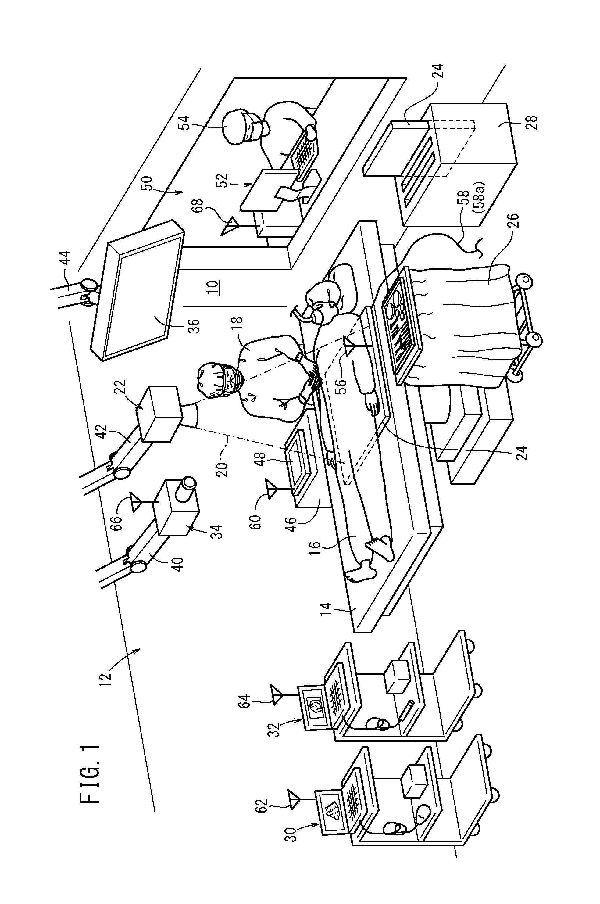

Radiography system

a technology of radiography and image capturing, which is applied in the field of radiographic image capturing system, can solve the problems of increasing radiologist's workload, unable to quickly complete a series of procedures, and unable to appropriately change the image capturing conditions of radiologists

Active Publication Date: 2014-09-18
FUJIFILM CORP
View PDF12 Cites 29 Cited by
  • Summary
  • Abstract
  • Description
  • Claims
  • Application Information

AI Technical Summary

Benefits of technology

The present invention is aimed at providing a radiographic image capturing system that can rapidly and appropriately change image capturing conditions and position the subject. The system includes an image storage portion for storing the captured images, which can be sent to the control apparatus even in cases where there is a defect in signal transmission / reception via the wired communication link. The control apparatus can also control the radiographic image capturing apparatus using the mobile apparatus as a transponder, in case the defect cannot be eliminated.

Problems solved by technology

Therefore, the radiologist may fail to appropriately change the image capturing conditions after he receives the verbal instruction from the doctor.
Therefore, the radiologist's workload is increased, and the radiologist cannot rapidly complete a series of the procedures between the interruption and restart of the fluorography.

Method used


Image

  • Radiography system
  • Radiography system
  • Radiography system

Examples


embodiment

Modifications of Embodiment

[0309]The medical system 10 of this embodiment is not limited to the above description, and may have the following structures (according to first to third modifications).

first modification

[0310]In the first modification of this embodiment, in a case where the doctor 18 clicks a desired area on the screen of the display portion 192 with a finger as shown in FIG. 15A, the next capturing of the image of the patient 16 is performed such that the clicked area is displayed in the center of the screen. Thus, in the image acquired by the next capturing, the clicked area is displayed in the center of the screen of the display portion 192 as shown in FIG. 15B. In the following description, the moving image acquired in the fluoroscopic image capturing is displayed on the screen of the display portion 192 in the same manner as FIG. 6A by way of example.

[0311]As shown in FIG. 15A, in a case where the moving fluorography image is displayed on the screen of the display portion 192 and the circled area containing the narrowed portion 224 is an area of concern 296 of the doctor 18, the doctor 18 clicks the area of concern 296 with a finger. The control portion 132 in the mobile appar...

second modification

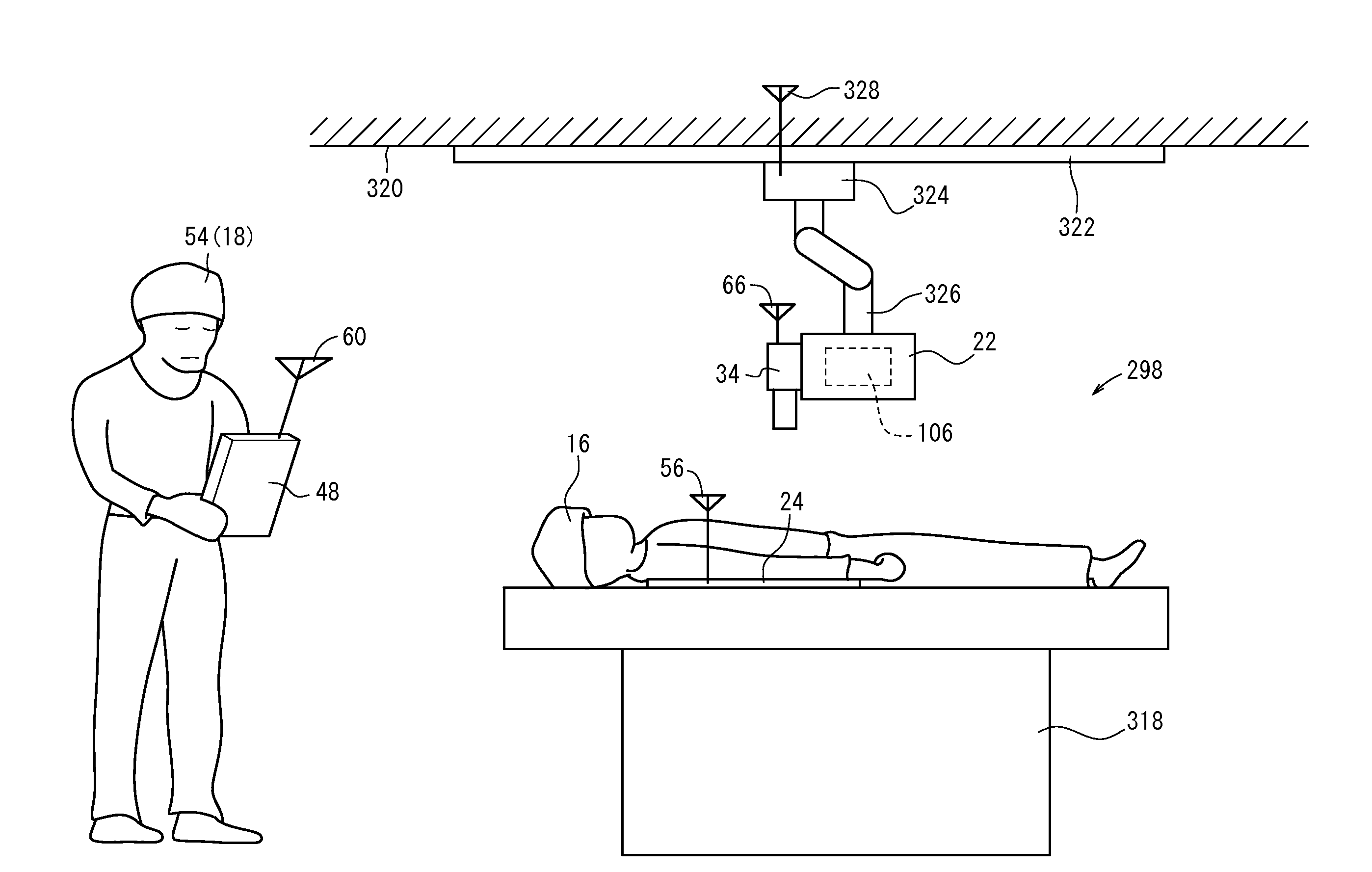
[0322]In the above description, the doctor 18 operates on the patient 16 in the operating room 12.

[0323]In the second modification of this embodiment, as shown in FIG. 16, in a case where the patient 16 lies down on a bed 300 in a patient room 298 or the like in the medical institution, the technician 54 or the doctor 18 carries a round cart 302 to the patient room 298 and performs therein a diagnosis of the patient 16 (such as the radiographic image capturing using the radiation source 106 and the radiographic image capturing apparatus 24).

[0324]In the round cart 302, a base unit 306 is disposed as a housing on a dolly 304. The console 52, which has a display operation portion 308 with the display portion 192, the operation portion 194, and the exposure switch 196 being integrated thereinto, is disposed in the base unit 306. Insertion slots, into which the radiographic image capturing apparatus 24 can be inserted, are formed on the base unit 306. The cradle 28 for charging the radi...


PUM


Abstract

This radiography system has a switching processing unit that switches the device that controls a radiation source and a radiography device to a control device or a portable apparatus. In a case where penetrative imaging has started, the switching processing unit switches the device that controls the radiation source and the radiography device from the control device to the portable apparatus.

Description

CROSS-REFERENCE TO RELATED APPLICATIONS AND PRIORITY CLAIM[0001]This application is a Continuation of International Application No. PCT / JP2012 / 080884 filed on Nov. 29, 2012, which was published under PCT Article 21(2) in Japanese, which is based upon and claims the benefit of priority from Japanese Patent Application No. 2011-262835 filed on Nov. 30, 2011, the contents all of which are incorporated herein by reference.TECHNICAL FIELD[0002]The present invention relates to a radiographic image capturing system capable of applying radiation to a subject and converting the radiation transmitted through the subject into a radiographic image.BACKGROUND ART[0003]Radiographic image capturing systems, which have a radiation source for applying radiation to a subject, a radiographic image capturing apparatus for converting the radiation transmitted through the subject into a radiographic image, and a control apparatus for controlling the radiation source and the radiographic image capturing a...

Claims


Application Information

Patent Timeline
Patent Type & Authority Applications(United States)
IPC IPC(8): A61B5/00G16H30/20G16H40/60
CPCA61B5/0071A61B1/00039A61B6/4233A61B6/4283A61B6/4405A61B6/4464A61B6/465A61B6/548A61B6/56A61B8/465A61B8/54A61B8/56A61B1/00016A61B1/00045A61B1/00006A61B1/0005A61B8/565G16H40/63G16H40/60G16H30/20G06F30/20
Inventor OHTA, YASUNORINISHINO, NAOYUKINAKATSUGAWA, HARUYASUIWAKIRI, NAOTOKITANO, KOUICHI
Owner FUJIFILM CORP
Features
  • Generate Ideas
  • Intellectual Property
  • Life Sciences
  • Materials
  • Tech Scout
  • Unparalleled Data Quality
  • Higher Quality Content
  • 60% Fewer Hallucinations
Learn More