Micro-incision iol and positioning of the iol in the eye

a micro-incision and positioning technology, applied in the field of intraocular lenses, can solve the problems of impairing the vision of patients, human eye diseases, etc., and achieve the effects of reducing post-surgical recovery time, reducing the size of the incision, and reducing the complexity of the surgical procedur

Active Publication Date: 2014-09-18
AMO GRONINGEN
View PDF4 Cites 25 Cited by
  • Summary
  • Abstract
  • Description
  • Claims
  • Application Information

AI Technical Summary

Benefits of technology

[0007]IOLs can be implanted in the eye to correct for a variety of vision defects. IOLs can be introduced in the eye through an incision made in the corneal layers and implanted in the capsular bag or in front of the capsular bag. Conventional IOL designs and insertion procedures enable IOLs to be inserted through incisions that range in size between 3.0 mm-12 mm. While conventional IOLs and methods of implantation provide the end result of treating the vision conditions in question, it is advantageous to reduce the size of the incision made to access the inside of the eye. Smaller incisions will reduce the complexity of the surgical procedure, reduce post-surgical recovery time and reduce patient discomfort. Certain embodiments disclosed herein include compact IOLs that are capable of being inserted through micro-incisions, such as, for example incisions that are a few hundred microns in size.

Problems solved by technology

A human eye can suffer diseases that impair a patient's vision.
For example, a cataract can increase the opacity of the lens, ultimately leading to blindness.

Method used


Image

  • Micro-incision iol and positioning of the iol in the eye
  • Micro-incision iol and positioning of the iol in the eye
  • Micro-incision iol and positioning of the iol in the eye

Examples


Embodiment Construction

[0019]It is to be understood that the figures and descriptions of the present invention have been simplified to illustrate elements that are relevant for a clear understanding of the present invention, while eliminating, for the purpose of clarity, many other elements found in typical lenses, lens systems and lens design methods. Those of ordinary skill in the arts may recognize that other elements and / or steps are desirable and may be used in implementing the embodiments described herein.

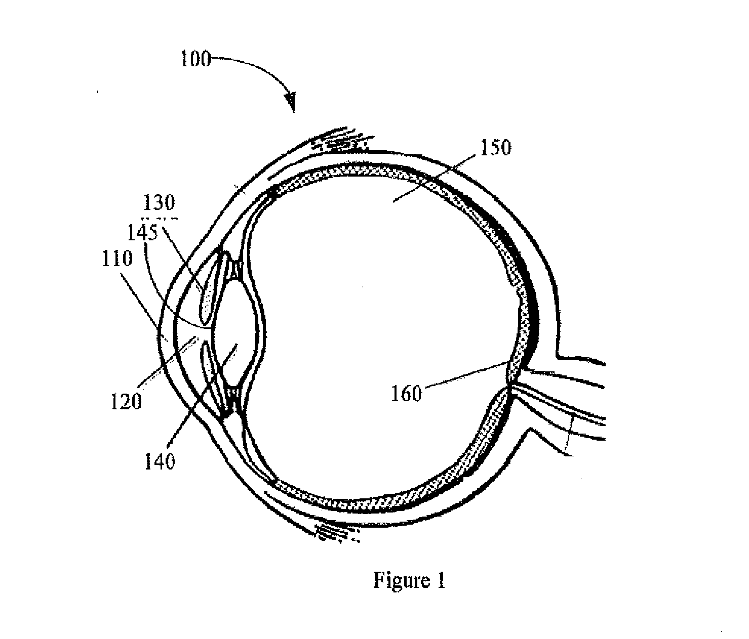
[0020]FIG. 1 is a schematic drawing of a human eye 100. Light enters the eye from the left of FIG. 1, and passes through the cornea 110, the anterior chamber 120, a pupil defined by the iris 130, and enters the lens 140. After passing through the lens 140, light passes through the vitreous chamber 150, and strikes the retina 160, which detects the light and converts it to a signal transmitted through the optic nerve to the brain (not shown).

[0021]The natural lens 140 is a transparent crystalline bi...


PUM


Abstract

An intraocular lens that is capable of being inserted through a micro-incision includes an optic having an anterior and a posterior surface and a plurality of projections extending from the anterior and posterior surfaces. The anterior and posterior surfaces include a recess. The optic is implanted such that a rim of the capsulorhexis is disposed in the recess such that the plurality of projections grip the capsular bag.

Description

CROSS-REFERENCES TO RELATED APPLICATIONS[0001]This application claims priority to U.S. Provisional Application No. 61 / 779,505 filed on Mar. 13, 2013, the entire contents of which are incorporated herein by reference.BACKGROUND[0002]1. Field of the Invention[0003]This invention relates generally to intraocular lenses, and more specifically, to compact intraocular lenses that can be implanted in the eye with a micro-incision.[0004]2. Description of the Related Art[0005]A human eye can suffer diseases that impair a patient's vision. For example, a cataract can increase the opacity of the lens, ultimately leading to blindness. To restore the patient's vision, the diseased lens may be surgically removed and replaced with an artificial lens, known as an intraocular lens, or IOL. As another example, to treat eye conditions such as myopia, hypermetropia or presbyopia, an intraocular lens can be surgically implanted in the eye to replace or supplement the natural eye.[0006]IOLs can be insert...

Claims


Application Information

Patent Timeline
Patent Type & Authority Applications(United States)
IPC IPC(8): A61F2/16
CPCA61F2002/1697A61F2/16A61F2/1648A61F2002/1681A61F9/007A61F2002/16905A61F2220/0016A61F2/1654A61F2/161A61F2/1656
Inventor WEEBER, HENDRIK A.NORRBY, SVERKERVAN DER MOOREN, MARRIE H.FRANSSEN, LUUK
Owner AMO GRONINGEN
Why Eureka
Try Eureka