Virtualization Congestion Control Framework

Active Publication Date: 2014-09-18
CENTURYLINK INTPROP
View PDF10 Cites 43 Cited by
  • Summary
  • Abstract
  • Description
  • Claims
  • Application Information

AI Technical Summary

Benefits of technology

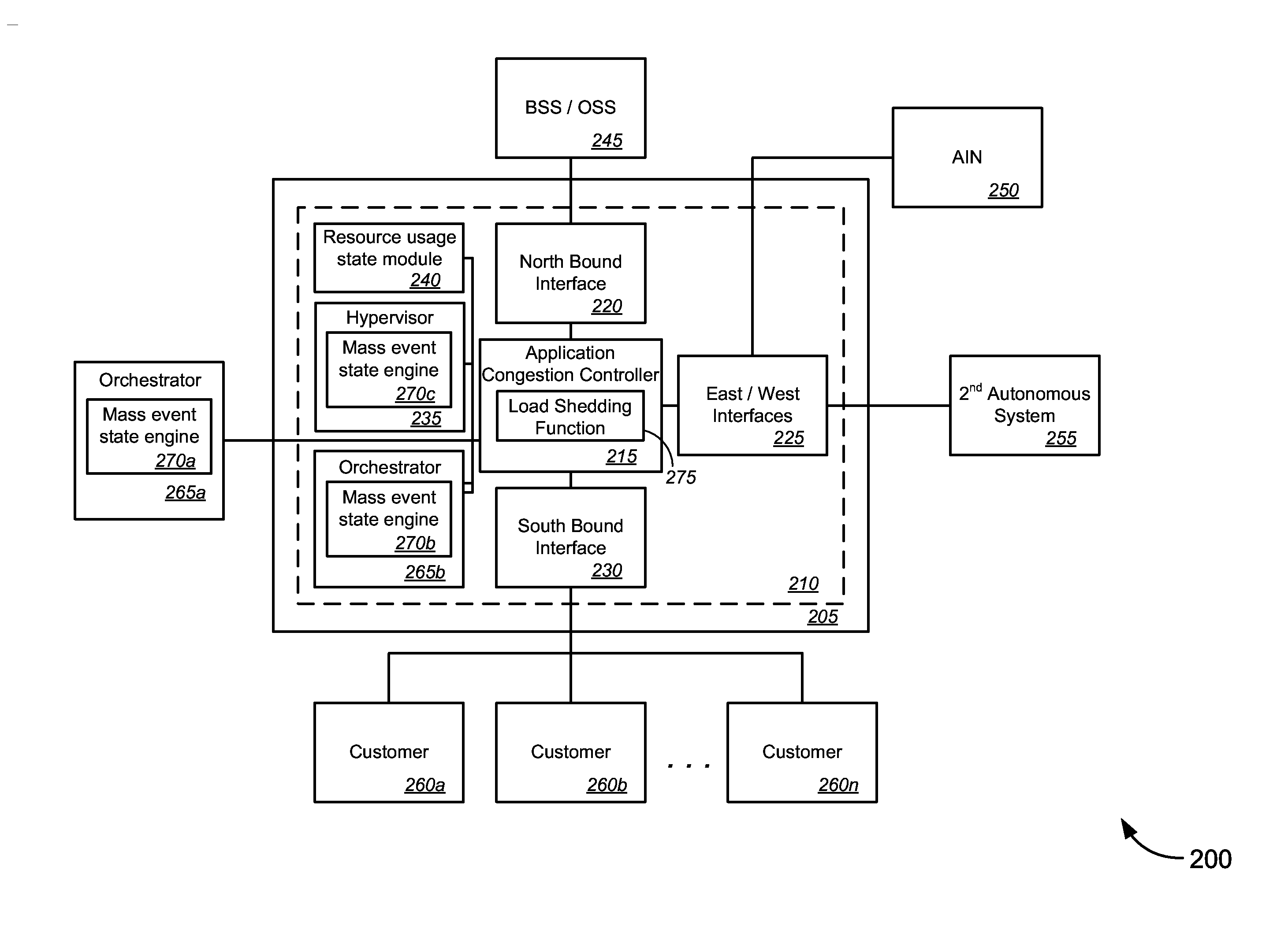
[0012]Various embodiments provide techniques for implementing a virtualization congestion control framework. In particular, in an environment in which one or more virtual machines (“VMs”) execute on a common hardware platform, a congestion control framework can coordinate resource utilization when being consumed by a plurality of applications (some of which might run within the same VM or different VMs on the same hardware platform). While conventional VM hypervisors provide some resource allocation features, congest

Problems solved by technology

In a virtual machine (“VM”) environment or cloud virtualized environment, such as in a telecommunications service provider system, congestion issues might arise where one or more applications might request more and more hardware resources, without end and without any means for monitoring the actual hardware (or hardware resource) constraints on the host system.
Without any checks on the resource allocation associated with the host system, the one or more applications might request more and more hardware resources until the host system finally and catastrophically crashes.
In other words, even though existing application congestion controllers and congestion control state machines might utilize the orchestrator(s) and/or hypervisor(s) to add resources, such elements do not have the functionality for receiving limitations from the cloud to perform push backs to bound and/or reduce the use of hardware resources, and thus cannot ensure that if the application is attacked or running over capacity the application will not crash the system.
In addition, even though different hardware from a single vendor might provide for load push back mechanisms and/or dedicated scan rates at the north, south, east, and west bound interfaces of an application congestion controller, by using a protocol with an intelligent device for “buffer monitoring,” such conge

Method used


Image

  • Virtualization Congestion Control Framework
  • Virtualization Congestion Control Framework
  • Virtualization Congestion Control Framework

Examples


Embodiment Construction

[0044]While various aspects and features of certain embodiments have been summarized above, the following detailed description illustrates a few exemplary embodiments in further detail to enable one of skill in the art to practice such embodiments. The described examples are provided for illustrative purposes and are not intended to limit the scope of the invention.

[0045]In the following description, for the purposes of explanation, numerous specific details are set forth in order to provide a thorough understanding of the described embodiments. It will be apparent to one skilled in the art, however, that other embodiments of the present invention may be practiced without some of these specific details. In other instances, certain structures and devices are shown in block diagram form. Several embodiments are described herein, and while various features are ascribed to different embodiments, it should be appreciated that the features described with respect to one embodiment may be i...


PUM


Abstract

Novel tools and techniques are provided for implementing a virtualization congestion control framework. In one aspect, a method might include a hypervisor assigning application resources of a virtual machine (“VM”), which operates on a host computing system, with maximum allowable settings to each software application to be executed on the VM. The hypervisor or an orchestrator might determine a running mode of the host computing system, and might execute the software application(s) using running mode attributes of the determined running mode. The hypervisor or the orchestrator might monitor application resource utilization, and, based on a determination that application resource utilization has changed, might modify allocation of application resources to each of the software application(s). In some cases, the hypervisor or the orchestrator might monitor for mass congestion indicators, and, based on a determination that a mass congestion indicator is present, might modify the running mode of the host computing system.

Description

CROSS-REFERENCES TO RELATED APPLICATIONS[0001]This application claims priority to U.S. Patent Application Ser. No. 61 / 788,256 (the “'256 application”), filed Mar. 15, 2013 by Michael K. Bugenhagen (attorney docket no. 020370-009601US), entitled, “Virtualization Congestion Control Framework.”[0002]This application is also a continuation-in-part of U.S. patent application Ser. No. 14 / 060,450 (the “'450 application”), filed Oct. 22, 2013 by Michael K. Bugenhagen (attorney docket no. 020370-009600US), entitled, “Virtualization Congestion Control Framework,” which also claims priority to the '256 application.[0003]The entire disclosure of each of these applications is incorporated herein by reference in its entirety for all purposes.COPYRIGHT STATEMENT[0004]A portion of the disclosure of this patent document contains material that is subject to copyright protection. The copyright owner has no objection to the facsimile reproduction by anyone of the patent document or the patent disclosur...

Claims


Application Information

Patent Timeline
IPC IPC(8): G06F9/455G06F9/50
CPCG06F9/50G06F9/45533G06F9/45558G06F9/5077G06F2009/45583G06F2009/45591G06F9/5016
Inventor BUGENHAGEN, MICHAEL K.
Owner CENTURYLINK INTPROP
Why Eureka
Try Eureka