Fuel injection system having a fuel-carrying component, a fuel injector and a suspension

a fuel injection system and component technology, applied in the direction of sleeve/socket joint, machine/engine, mechanical apparatus, etc., can solve the problems of obstructing and disturbing the overall noise of the engine, vibrations may be transmitted between the fuel injector and the connection fitting, and the snap ring and the inflow fitting, so as to achieve the effect of reliably fastening the annular element and optimizing the stress of elastically deformable elements

Active Publication Date: 2014-09-25
ROBERT BOSCH GMBH
View PDF4 Cites 4 Cited by
  • Summary
  • Abstract
  • Description
  • Claims
  • Application Information

AI Technical Summary

Benefits of technology

[0005]The suspension according to the present invention and the fuel injection system according to the present invention have the advantage of allowing for an improved suspension of the fuel injector on the fuel-carrying component. It is possible in this connection to reduce noise by way of a specific decoupling. Specifically, a soft connection of the fuel injector to the fuel-carrying component may be achieved, which allows for a noise reduction of the entire system including the fuel injection system.
[0009]It is particularly advantageous, however, for the elastically deformable element on the one hand to abut against a support surface provided in the area of the receiving space and on the other hand to but against the annular element. As a result, a high mechanical stability of the connection between the annular element and the fuel fitting may be achieved. In addition, the supporting surface may be advantageously developed on the annular element so as to avoid mechanical stress on the elastically deformable element by bending or the like and to allow at the same time for an introduction of force that is as homogeneous as possible.
[0010]In this connection, it is also advantageous for the connecting body to have a shoulder in the area of the receiving space, on which the supporting surface of the connecting body is developed, and for the opening of the connecting body to be developed within the shoulder. This allows for a compact design, in which the connecting body may be developed as a cup-shaped connecting body.
[0011]It is also advantageous for the fuel fitting insertable into the receiving space of the connecting body to be supportable along the axis on the connecting body via the annular element and another elastically deformable element in a direction opposite to the direction toward the opening of the connecting body. A support on both sides for the annular element is thereby formed on the connecting body. It is furthermore advantageous in this regard for the additional elastically deformable element on the one hand to abut against another support surface of the connecting body provided in the area of the receiving space and, on the other hand, to but against the annular element. This also achieves a reduction of mechanical stress by bending or the like of the elastically deformable element and allows for a homogeneous transmission of force between the annular element and the additional elastically deformable element. It is particularly advantageous in this regard for the annular element to be developed as an annular plate-shaped element.
[0013]The elastically deformable element and the additional elastically deformable element are preferably developed in disk-shaped fashion. This allows for an optimized stress of the elastically deformable elements along the axis of the receiving space of the connecting body.
[0014]It is moreover advantageous for the fuel fitting of the fuel injector to have an annular recess into which the annular element is inserted in the installed state, and for the annular element to be fixed in place on both sides in the annular recess of the fuel fitting along the axis of the receiving space. For this purpose, the annular recess may be developed in particular as an annular groove. This makes it possible to fasten the annular element reliably on the fuel fitting. Depending on the design of the suspension, this makes it possible to avoid a tilting of the fuel fitting relative to the axis of the receiving space. The fuel fitting is thereby prevented from touching the connecting body. At the same time this allows for a soft suspension. This furthermore makes it possible to ensure that no contact occurs in any operating state between a pole pot of the fuel injector and the cylinder head of the internal combustion engine.

Problems solved by technology

No. 10 2005 020 380 has the disadvantage that vibrations may be transmitted between the connection fitting, the snap ring and the inflow fitting.
In particular, vibrations may be transmitted from the fuel injector to the connection fitting.
Especially in the case of electromagnetic high-pressure fuel injectors, which may be used in Otto engines having direct injection, an obtrusive and disturbing contribution to the overall noise of the engine may occur, which may been described as valve ticking Such valve ticking arises from the rapid opening and closing of the fuel injector, in which the valve needle is displaced in a highly dynamic way to the respective end stops.
The impact of the valve needle on the end stops results in briefly active but very high contact forces which are transmitted via a housing of the fuel injector to the cylinder head and to a fuel distributor rail in the form of structure-borne noise and vibrations.
This results in a strong noise development on the cylinder head and on the fuel distributor rail.

Method used


Image

  • Fuel injection system having a fuel-carrying component, a fuel injector and a suspension
  • Fuel injection system having a fuel-carrying component, a fuel injector and a suspension
  • Fuel injection system having a fuel-carrying component, a fuel injector and a suspension

Examples


Embodiment Construction

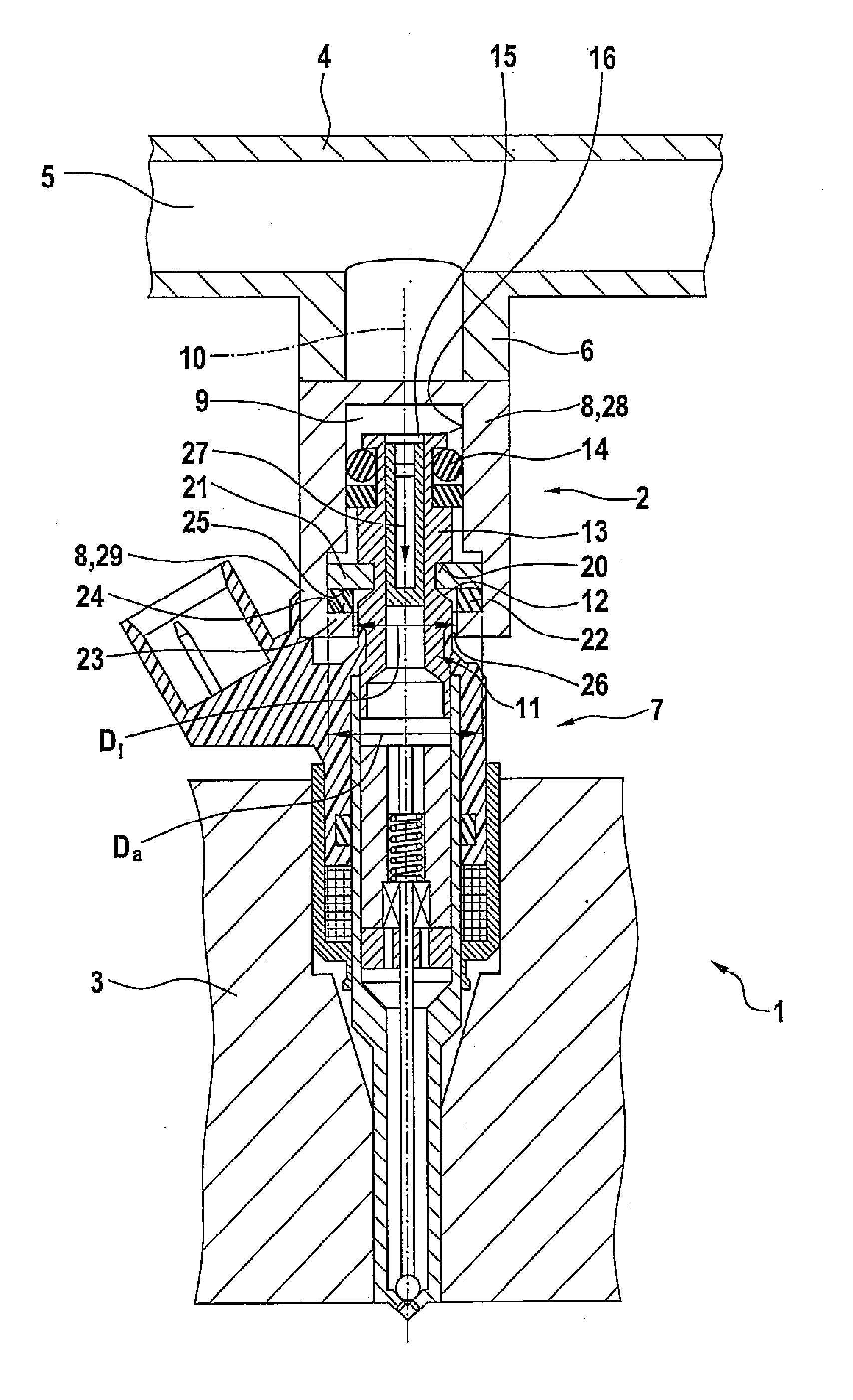
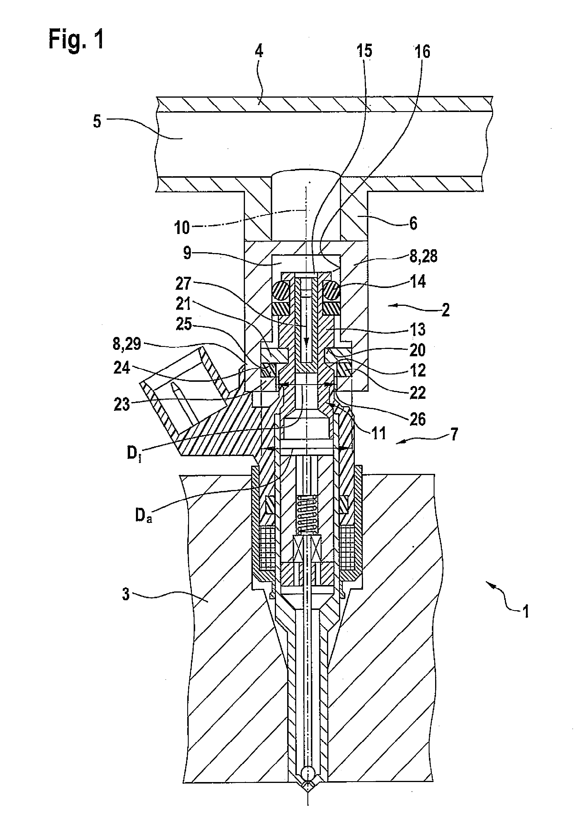
[0017]FIG. 1 shows a fuel injection system 1 having a suspension 2 corresponding to a first exemplary embodiment and an internal combustion engine 3 in an excerpted, schematic sectional view. Fuel injection system 1 may be particularly used for high-pressure injection in internal combustion engines 3. In particular, fuel injection system 1 may be used in mixture-compressing internal combustion engines 3 having externally supplied ignition. Suspension 2 is particularly suitable for such a fuel injection system 1.

[0018]Fuel injection system 1 has a fuel-carrying component 4, which in this exemplary embodiment is developed as a fuel distributor 4, in particular a fuel distributor rail 4. Fuel distributor 4 has an elongated fuel chamber 5, into which highly pressurized fuel is conveyed by a high-pressure pump (not shown). Fuel distributor 4 has multiple outlets 6, of which only outlet 6 is shown in FIG. 1 for the sake of simplifying the representation. One fuel injector 7 is situated at...


PUM


Abstract

A suspension for fuel injection systems is used for connecting a fuel injector to a fuel-carrying component. A connecting body having a receiving space is provided for this purpose. The connecting body has an opening, via which a fuel fitting of the fuel injector is insertible at least partially into the receiving space of the connecting body. Furthermore, an annular element and an elastically deformable element are provided. Fuel fitting is supported via the annular element and the elastically deformable element along an axis of the receiving space of the connecting body. A fuel injection system having such a suspension is also indicated. The suspension allows for a soft coupling of the fuel injector to the fuel-carrying component at a desired target stiffness.

Description

FIELD OF THE INVENTION[0001]The present invention relates to a suspension for fuel injection systems for the connection of a fuel injector to a fuel-carrying component and a fuel injection system having such a suspension. The present invention specifically relates to the field of fuel injection systems for mixture-compressing internal combustion engines having externally supplied ignition.BACKGROUND INFORMATION[0002]German Published Patent Appln. No. 10 2005 020 380 describes a fuel injection device having a noise-decoupling construction. The known fuel injection device includes a fuel injector, a receiving borehole for the fuel injector in a cylinder head and a fuel distributor line having a connection fitting. The fuel injector is inserted into the connection fitting in a partially overlapping manner. In one possible development, a slotted snap ring is provided, which engages into a tapered section of an inflow fitting of the fuel injector. A groove is furthermore provided in the ...

Claims


Application Information

Patent Timeline
Patent Type & Authority Applications(United States)
IPC IPC(8): F02M61/14F16L21/02
CPCF16L21/02F02M61/14F02M2200/09F02M2200/856
Inventor FISCHER, MICHAELKNORPP, MICHAELRIEMER, MARTINHORST, HANS-GEORGGLASER, ANDREASROGLER, PHILIPPHERRMANN, JANREHWALD, ANDREASMAYER, MICHAELSCHEEF, VOLKERREINHARDT, WILHELM
Owner ROBERT BOSCH GMBH
Why Eureka
Try Eureka