Exploration method and system for detection of hydrocarbons with an underwater vehicle

a technology of hydrocarbons and underwater vehicles, applied in the field of hydrocarbon exploration, can solve the problems of inability to provide accurate assessments, inability to distinguish the presence and type of hydrocarbons from other fluids, and lack of technology fidelity to provide accurate assessments

Active Publication Date: 2014-09-25
KNIGHT BRENT R
View PDF3 Cites 19 Cited by
  • Summary
  • Abstract
  • Description
  • Claims
  • Application Information

AI Technical Summary

Problems solved by technology

Hydrocarbon reserves are becoming increasingly difficult to locate and access, as the demand for energy grows globally.
However, this technology may lack the required fidelity to provide accurate assessments of the presence and volume of subsurface hydrocarbon accumulations due to poor imaging of the subsurface, particularly with increasing depth where acoustic impedence contrasts that cause DHIs are greatly diminished or absent.
Additionally, it is difficult to differentiate the presence and types of hydrocarbons from other fluids in the subsurface by such remote measurements.
Current geophysical, non-seismic hydrocarbon detection technologies, such as potential fields methods like gravity or magnetics or the like, provide coarse geologic subsurface controls by sensing different physical properties of rocks, but lack the fidelity to identify hydrocarbon accumulations.
These tools may provide guidance on where in a basin seismic surveys should be conducted, but do not significantly improve the ability to confirm the presence of hydrocarbon seeps or subsurface hydrocarbon accumulations.
Other non-seismic hydrocarbon detection technologies may include geological extrapolations of structural or stratigraphic trends that lead to prospective hydrocarbon accumulations, but cannot directly detect these hydrocarbon accumulations.
However, these techniques are limited as well.
While quite valuable, these technologies have limitations in fidelity, specificity, coverage, and cost.
Unfortunately, as the ROV has to be manually controlled, a large number of operator hours are required to conduct such a pipeline survey.
However, this reference appears to rely only upon a methane sniffer for leakage detection, which can result in reliability problems due to the lack of additional sensor information.
Despite these different technologies, many frontier hydrocarbon exploration ventures result in failures.
In particular, these failures are attributed to an inability to fully evaluate, understand, and appropriately risk the hydrocarbon system components, from source to seeps (e.g., source presence and maturity, migration, accumulation and leakage).

Method used


Image

  • Exploration method and system for detection of hydrocarbons with an underwater vehicle
  • Exploration method and system for detection of hydrocarbons with an underwater vehicle
  • Exploration method and system for detection of hydrocarbons with an underwater vehicle

Examples


Embodiment Construction

[0021]In the following detailed description section, the specific embodiments of the present disclosure are described in connection with preferred embodiments. However, to the extent that the following description is specific to a particular embodiment or a particular use of the present disclosure, this is intended to be for exemplary purposes only and simply provides a description of the exemplary embodiments. Accordingly, the disclosure is not limited to the specific embodiments described below, but rather, it includes all alternatives, modifications, and equivalents falling within the true spirit and scope of the appended claims.

[0022]Various terms as used herein are defined below. To the extent a term used in a claim is not defined below, it should be given the broadest definition persons in the pertinent art have given that term as reflected in at least one printed publication or issued patent.

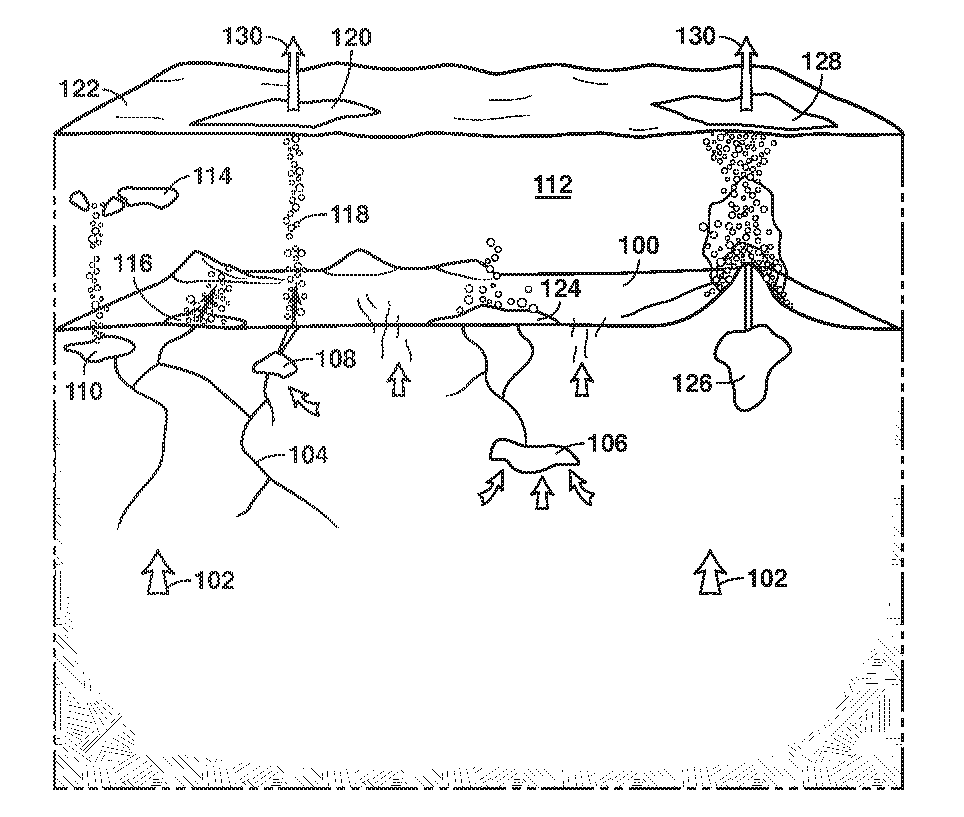
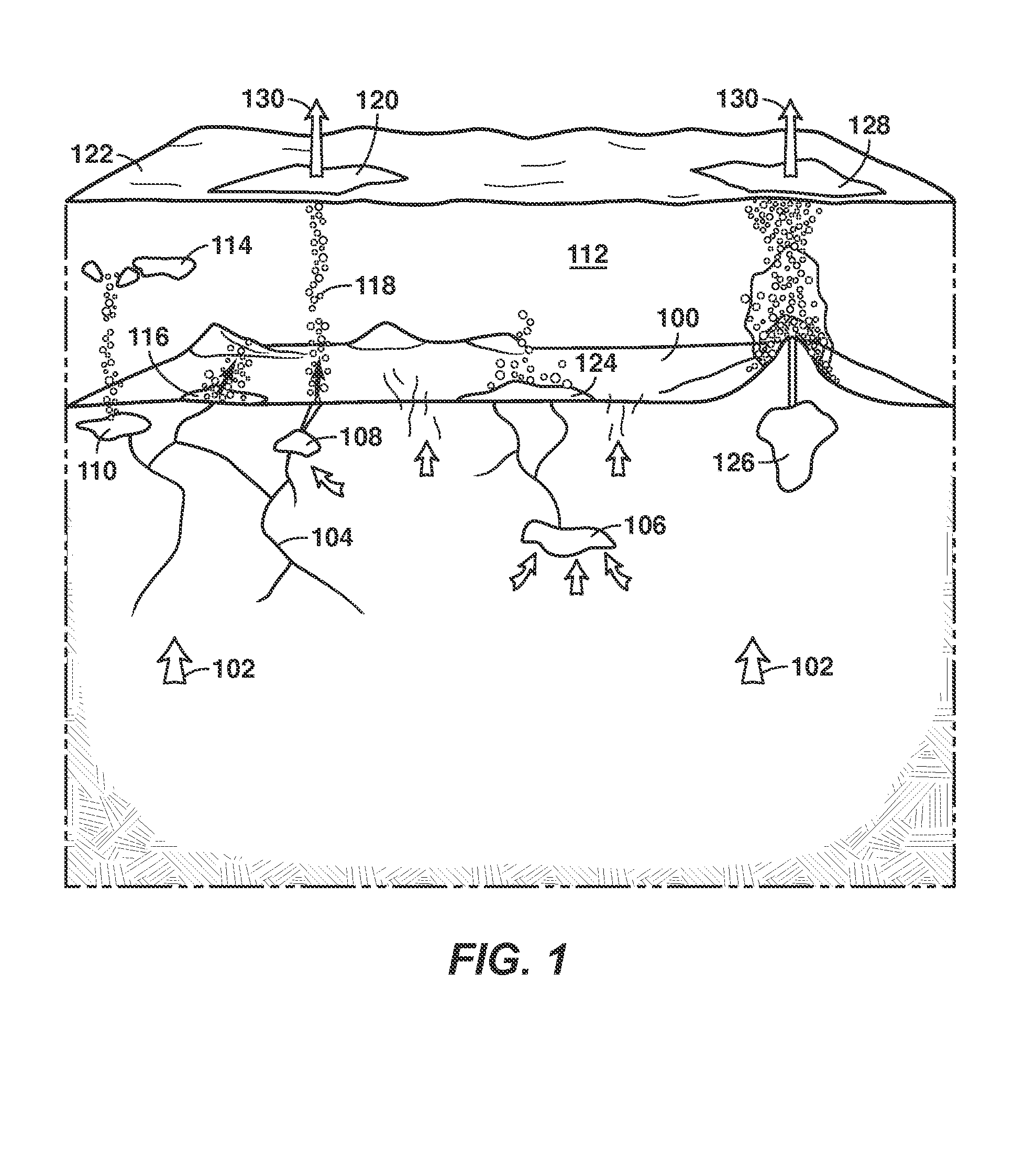
[0023]To begin, a seep is a natural surface leak of gas and / or oil. The hydrocarbon (...


PUM


Abstract

A method for detecting hydrocarbons with an underwater vehicle equipped with one or more measurement components is described. The method includes navigating the UV within the body of water; monitoring the body of water with measurement components associated with the UV to collect measurement data. The collected data from the UV is used to determine whether hydrocarbons are present and at the location.

Description

CROSS REFERENCE TO RELATED APPLICATION[0001]This application claims the priority benefit of National Stage of International Application No. PCT / US2012 / 52542, filed 27 Aug. 2012, which claims priority benefit of U.S. Provisional Patent Application 61 / 558,822 filed 11 Nov. 2011 entitled METHOD FOR DETERMINING THE PRESENCE AND LOCATION OF A SUBSURFACE HYDROCARBON ACCUMULATION AND THE ORIGIN OF THE ASSOCIATED HYDROCARBONS, the entirety of which is incorporated by reference herein. This application also claims the benefit of U.S. Provisional Patent Application 61 / 595,394 filed 6 Feb. 2012, entitled A METHOD TO DETERMINE THE LOCATION, SIZE AND IN SITU CONDITIONS IN A HYDROCARBON RESERVOIR WITH ECOLOGY, GEOCHEMISTRY, AND COLLECTIONS OF BIOMARKERS, the entirety of which is incorporated by reference herein. This application also claims the benefit of U.S. Provisional Patent Application 61 / 616,813 FILED 28 Mar. 2012, entitled METHOD FOR DETERMINING THE PRESENCE AND VOLUME OF A SUBSURFACE HYDR...

Claims


Application Information

Patent Timeline
Patent Type & Authority Applications(United States)
IPC IPC(8): G01V8/02G01V5/00
CPCG01V9/007G01N1/00G01N29/14G01V1/38G01N33/241G01V8/02G01V9/005G01V5/00G01V3/08B63G8/001G01V11/00G01J3/0289G01N21/3103G01N21/3504G01N21/645G01V8/00G01V3/081
Inventor POTTORF, ROBERT J.SRNKA, LEONARD J.BOND, WILLIAMDREYFUS, SEBASTIEN L.LAWSON, MICHAELMEURER, WILLIAM P.CHERNEY, DANIEL P.MAY, STEVEN R.POWELL, WILLIAM G.VANDEWATER, CHRISTOPHER J.ERTAS, MEHMET D.RUDOLPH, KURT W.RAMAN, SUMATHYREGBERG, AARON B.N'GUESSAN, A. LUCIEROBINSON, AMELIA C.
Owner KNIGHT BRENT R
Why Eureka
Try Eureka