Power Supply Module

a power supply module and power supply technology, applied in the field of power supply, can solve the problems of increasing material cost and labor cost of products, increasing the cost of existing power supply modules, and not easy to fill heat conducting materials

Active Publication Date: 2014-09-25
SUMIDA ELECTRIC H K COMPANY
View PDF6 Cites 1 Cited by
  • Summary
  • Abstract
  • Description
  • Claims
  • Application Information

AI Technical Summary

Benefits of technology

[0005]Based on the above, in order to solve the above problems in the prior art, the objective of the present disclosure is to provide a power supply module, which can conveniently fill the heat conducting material so as to prevent the side wall of the from being damaged to avoid yield problem and quality problem of product.

Problems solved by technology

One common practice to achieve the above objective is to assemble the above individual electronic components together by a certain circuit connection respectively, which generally takes a larger space, and results in an increase of material cost and labor cost of products.
However, when the miniaturization is achieved, the existing power supply module might be subject to a defect caused by heat cycling or thermal cycling, so the applicant makes improvements in the power supply module that the coil body is enclosed in and around a magnetic core, a recess is provided on at least one side surface of the magnetic core, a heat conducting material is added in the recess between the electronic component and the magnetic core so as to provide better heat transfer characteristics from electronic component to ambient.
Though the structure improves the heat transfer characteristics, it brings another potential problem that it is not easy to fill the heat conducting material because a relatively closed space (or air bubble) may be formed in the recess when filling the heat conducting material and the side wall of the recess may be damaged by the high temperature expansion of the heat conducting material after filling the heat conducting material so as to reduce the quality and yield of the power product.

Method used


Image

  • Power Supply Module
  • Power Supply Module
  • Power Supply Module

Examples


embodiment 1

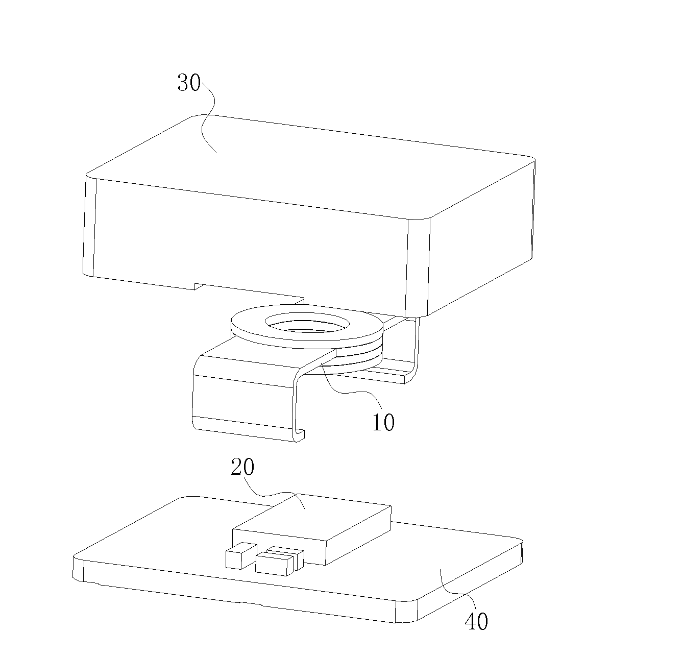
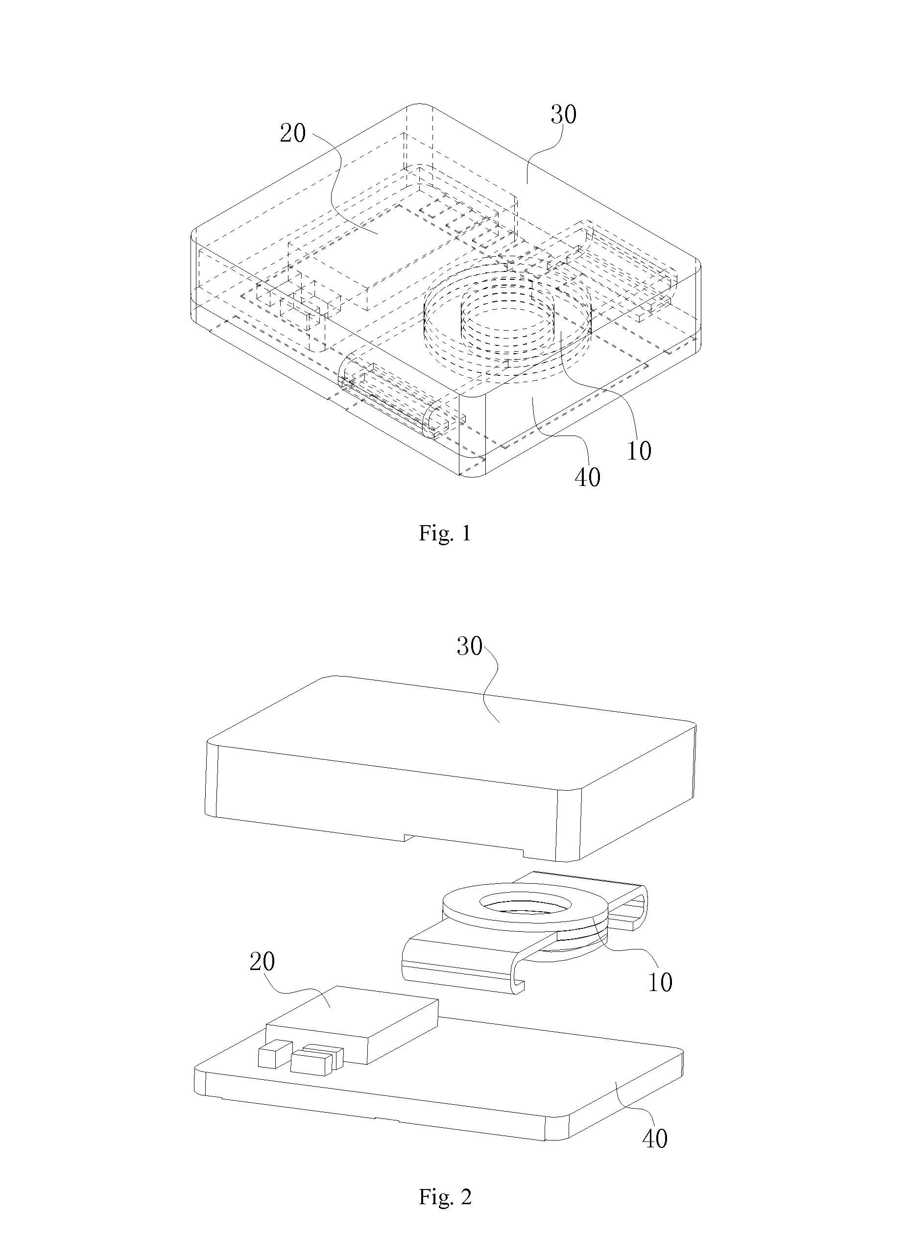
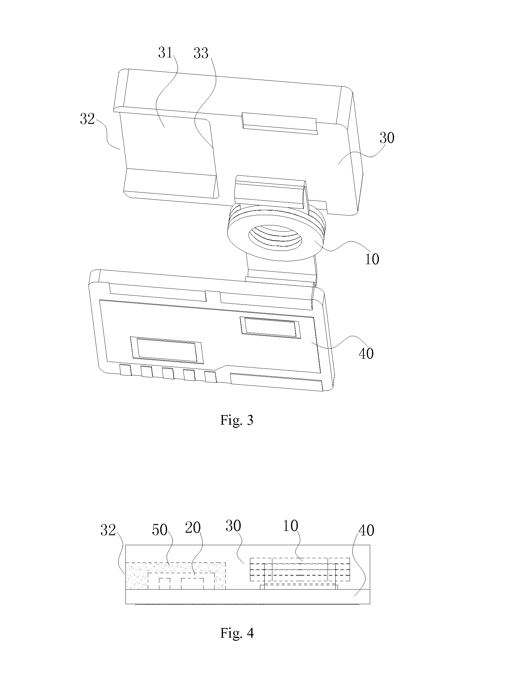
[0061]As shown in FIGS. 1-5, a power supply module includes: a coil including a coil body and connecting terminals; an electronic component including at least an integrated circuit chip; a magnetic core configured to enclose in and around the coil body, wherein a recess is provided on at least one side surface of the magnetic core, the electronic components are located in the recess, and an opening is provided on at least one side wall of the recess; a connector configured to be tightly attached to and cover the side surface where the recess is, and be electrically connected with the coil and the electronic component; and a heat conducting material provided in the recess and configured to cover the electronic component and to secure the magnetic core to the electronic component and the connector.

[0062]The magnetic core includes a main body side and a recess side, and the recess is located on the recess side. The coil is located in the main body side, the recess is located on the sid...

embodiment 2

[0067]As shown in FIGS. 6-10, the principle of the embodiment 2 is the same as that of the Embodiment 1, while the difference is that: in the embodiment 2, there are three openings which are located on the opposite side and two adjacent sides of the inner side wall respectively. The advantage of the embodiment 2 is the same as that of the Embodiment 1, so it's not described in detail here to avoid repetition.

embodiment 3

[0068]As shown in FIGS. 11-15, the principle of the embodiment 3 is the same as that of the Embodiment 1, while the differences are that: in the embodiment 3, the coil is located in the main body side, the recess is located beneath the coil, and the coil and the recess are arranged in an up-down (or top-bottom) positional relationship; the edge of at least one side of the main body side extends to the recess side and forms the side wall; and the opening is provided between two opposite side walls; and the width of the opening can be adjusted in the range of equal to or smaller than the width of the corresponding main body side. The advantage of the embodiment is the same as that of the Embodiment 1, so it's not described in this to avoid repetition.


PUM

PropertyMeasurementUnit
heat conductingaaaaaaaaaa
widthaaaaaaaaaa
inductanceaaaaaaaaaa

Abstract

A power supply module is disclosed. the power supply module includes a coil including a coil body and connecting terminals; an electronic component including at least an integrated circuit chip; a magnetic core configured to enclose in and around the coil body, wherein a recess is provided on at least one side surface of the magnetic core, the electronic components are located in the recess, and an opening is provided on at least one side wall of the recess; a connector configured to be tightly attached to and cover the side surface where the recess is provided, and be electrically connected with the coil and the electronic component; and a heat conducting material provided in the recess and configured to cover the electronic component.

Description

FIELD OF THE INVENTION[0001]The present disclosure relates generally to the field of power supply, and particularly to a power supply module.BACKGROUND OF THE INVENTION[0002]In the field of electronic products, in order to provide an accurate voltage and an accurate current for an operation of an electronic product, electronic components such as inductance, capacitance, resistance and integrated circuit chip, are integrated into one power supply module, using, for example, Power Supply in Package (PSiP) technology, to perform voltage or current conversion. One common practice to achieve the above objective is to assemble the above individual electronic components together by a certain circuit connection respectively, which generally takes a larger space, and results in an increase of material cost and labor cost of products.[0003]However, when the miniaturization is achieved, the existing power supply module might be subject to a defect caused by heat cycling or thermal cycling, so ...

Claims


Application Information

Patent Timeline
Patent Type & Authority Applications(United States)
IPC IPC(8): H01F27/02H01F27/22
CPCH01F27/22H01F27/025H01F27/306H01F27/40
Inventor MALCOLM, DOUGLAS JAMESLIU, YANFEIZHANG, GUOPING
Owner SUMIDA ELECTRIC H K COMPANY
Why Eureka
Try Eureka