Artificial turf barrier with artificial turf edge

Inactive Publication Date: 2014-09-25
GUENTNER HERIBERT +1
View PDF12 Cites 9 Cited by
  • Summary
  • Abstract
  • Description
  • Claims
  • Application Information

AI Technical Summary

Benefits of technology

[0030]According to an advantageous embodiment, a natural bottom side can be provided on the connecting grid intended to grow together with the natural lawn. This may enhance stability.
[0031]In a straight artificial turf barrier it may be advantageous to have a connecting grid having a width of about 4 to 5 cm and extending over the entire length of the artificial turf barrier. Thus, an area of sufficient size can be provided which can grow together with the natural lawn.
[0032]According to an embodiment of the invention, the artificial turf can be applied at a width of about 7 cm to the component over the entire length thereof by back injection molding. Straight artificial turf barriers can also be manufactured in this way easily and quickly, simultaneously providing for a robust and durable connection.
[0033]It may be advantageous for the artificial turf barrier to be made of thermoplastic synthetic resin or other suitable plastics or polymers. This may be advantageous with regard to the use outdoors and in wet grounds, as said materials withstand such conditions withou

Problems solved by technology

Apart from the above-described disadvantages, certain lawn limitations imply further problems which are not even mentioned in the above-cited documents.
However, when the nozzle is overgrown with grass said grass or similar weeds obstruct the system so that the water cannot be di

Method used


Image

  • Artificial turf barrier with artificial turf edge
  • Artificial turf barrier with artificial turf edge
  • Artificial turf barrier with artificial turf edge

Examples


Example

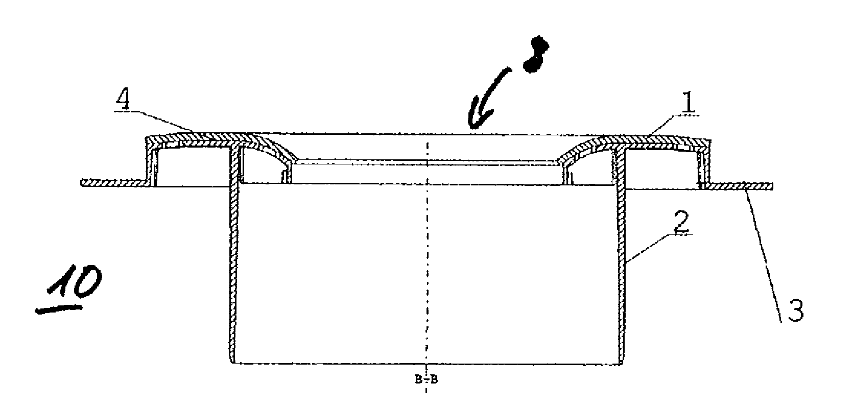
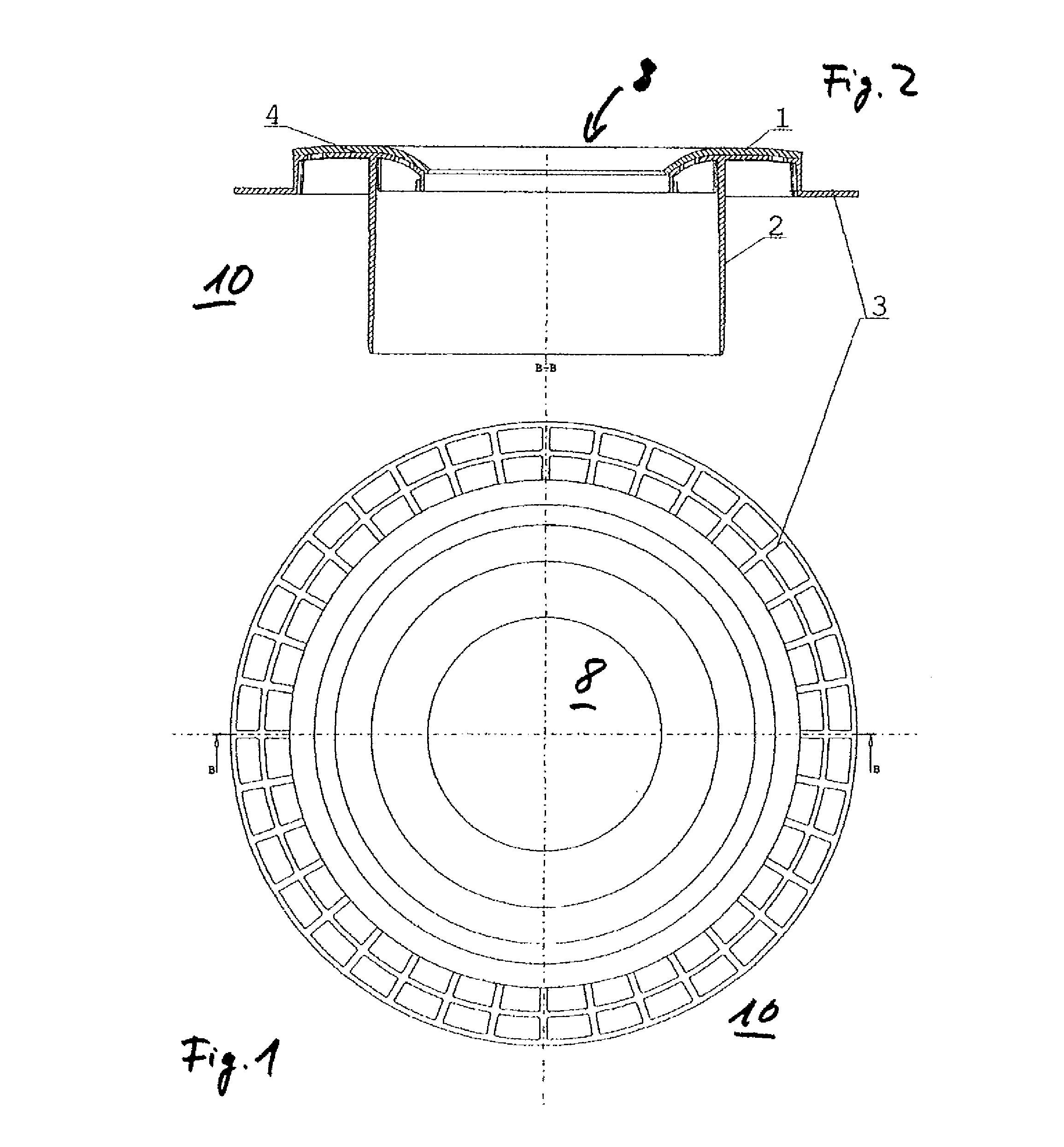
[0044]FIG. 1 is a top view of a first embodiment of an artificial turf barrier 10 according to the invention. As can sometimes be more apparent in FIG. 2, the artificial turf barrier 10 comprises artificial turf 1, a lawn barrier 2, a connecting grid 3, and a connecting area 4 for the artificial turf.

[0045]The artificial turf barrier 10 consists of a round growth barrier 2 which projects about 8 cm deep into the soil and also serves as a stabilizing element. The center thereof is provided with a round cut-out 8 (in the embodiment of a diameter of approx. 12 to 13 cm), to allow a nozzle of an irrigation system (not shown) to distribute water properly. As already mentioned, the artificial turf barrier may also be closed permanently or temporarily, e.g. by lids of flaps. Artificial turf 1 slopes towards the center by about 15 mm. Bonding area 4 has a diameter of about 25 to 30 cm, the horizontal connecting grid 3 is applied about 2 to 3 cm underneath the artificial turf bonding area 4 ...


PUM

PropertyMeasurementUnit
Lengthaaaaaaaaaa
Lengthaaaaaaaaaa
Lengthaaaaaaaaaa

Abstract

An artificial turf barrier including a lawn barrier, an artificial turf, and a connecting area for the artificial turf. A connecting grid is also provided. A method for manufacturing an artificial turf barrier including a lawn barrier and a connecting grid, the lawn barrier and the connecting grid being formed by injection molding. An artificial turf portion cut to size is inserted into an injection mold and the lawn barrier and the connecting grid are non-detachably combined with the artificial turf portion during injection molding.

Description

FIELD OF THE INVENTION[0001]The invention relates to an artificial turf barrier including a lawn barrier, artificial turf and a connecting area for the artificial turf. The invention also relates to a method for producing such an artificial turf barrier including a lawn barrier and a connecting grid, the lawn barrier and the connecting grid being formed by injection molding.BACKGROUND OF THE INVENTION[0002]Artificial turf limitations or borders are known, e.g. from DE 88 16 399 U1 which discloses an element for limiting lawn areas. Said element includes a high wedge-shaped portion which is to be forced into the soil. The wider side of this wedge-shaped portion is provided with a plate to which an artificial lawn attachment has been applied. The disclosed element is disadvantageous in that said plate is described to be several centimeters thick and rest on the soil. For lawn areas of low grass height, for instance golf courses where the grass is partially just a few millimeters tall,...

Claims


Application Information

Patent Timeline
IPC IPC(8): E01C13/08B29C45/14A01G9/28
CPCA01G1/08E01C13/08B29C45/14467A01G9/28
Inventor GUENTNER, HERIBERTHUBER, ANTON
Owner GUENTNER HERIBERT
Why Eureka
Try Eureka