Control device for vehicle drive device

a control device and driving device technology, applied in vehicle position/course/altitude control, process and machine control, instruments, etc., can solve the problem of the difference in rotational speed between the engagement members and achieve the effect of suppressing the reduction of durability of the second engagement devi

Active Publication Date: 2014-09-25
AISIN AW CO LTD
View PDF3 Cites 19 Cited by
  • Summary
  • Abstract
  • Description
  • Claims
  • Application Information

AI Technical Summary

Benefits of technology

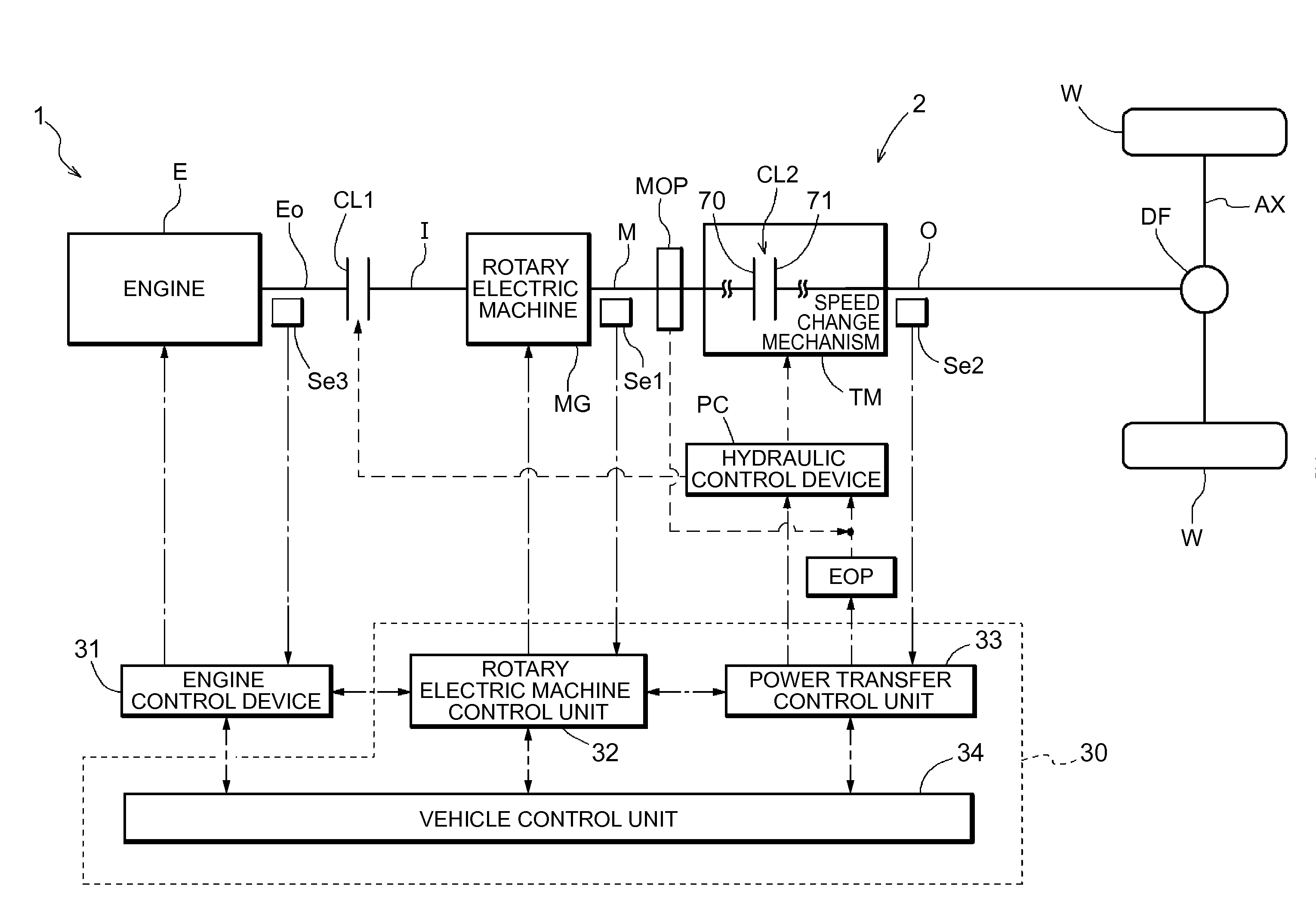
[0007]Thus, it is desirable to provide a control device for a vehicle drive device capable of starting a vehicle responsively in response to a request to start the vehicle and suppressing a reduction in durability of a second engagement device due to heat while securing working oil for both a first engagement device and the second engagement device in the case where the request to start the vehicle is provided with an internal combustion engine rotating and with both the first engagement device and the second engagement device disengaged.

Problems solved by technology

However, there is a difference in rotational speed between engagement members of the second engagement device when the second engagement device is engaged.
In addition, the technology according to Patent Document 1 relates to control for the two engagement devices at the start with rotation of the internal combustion engine stopped, and Patent Document 1 does not specifically describe or support control for the two engagement devices at the start with the internal combustion engine rotating.

Method used


Image

  • Control device for vehicle drive device
  • Control device for vehicle drive device
  • Control device for vehicle drive device

Examples


first example

[0088]The time-staggered engagement control will be described below with reference to a first example illustrated in the time chart of FIG. 4.

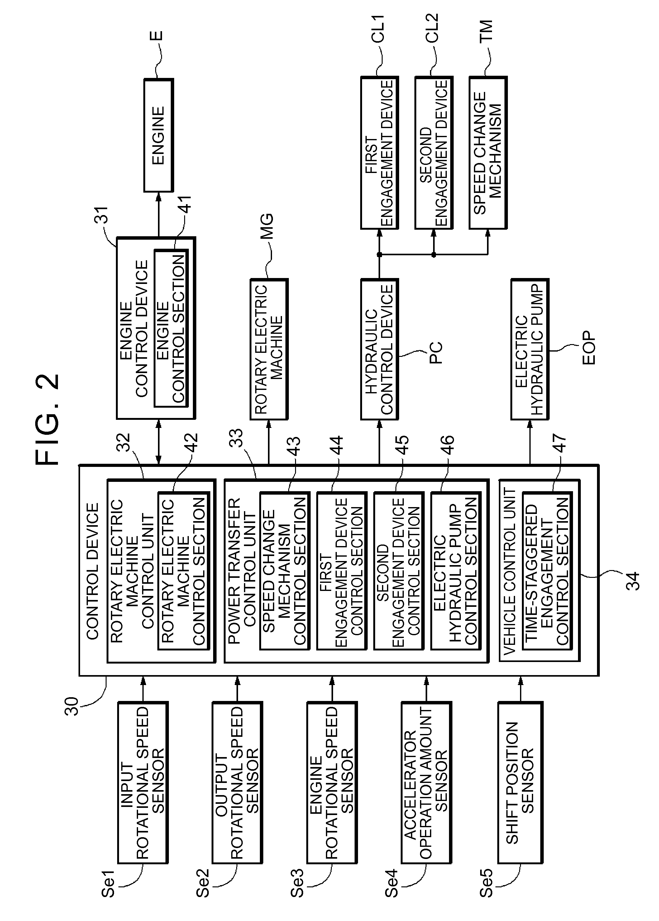
[0089]The time-staggered engagement control section 47 starts a sequence of time-staggered engagement control (time t11) by determining that the control start conditions are met in the case where a change in shift range from a stop range to a running range is detected with the engine E rotating and with both the first engagement device CL1 and the second engagement device CL2 disengaged. In the embodiment, the stop range corresponds to the “neutral range N” and the “parking range”, and the running range corresponds to the “drive range D” and the “reverse drive range”. In the example illustrated in FIG. 4, a change in shift range from the “neutral range N” to the “drive range D” is detected.

[0090]Here, the phrase “the engine E is rotating” means that the engine E is operating with the engine output shaft Eo such as the crankshaft of the engine ...

second example

[0126]Next, the time-staggered engagement control will be described below with reference to a second example illustrated in the time chart of FIG. 5.

[0127]The second example is different from the first example in that the time-staggered engagement control section 47 is configured to control the second engagement device CL2 such that the second engagement device CL2 is brought into the slipping engagement state when the first engagement device CL1 transitions to the direct engagement state after the start of engagement of the first engagement device CL1.

[0128]The control performed by the time-staggered engagement control section 47 up to time t27 in the second example illustrated in FIG. 5 is the same as the control performed up to time t17 in the first example illustrated in FIG. 4, and thus the same description will not be repeated.

[0129]The time-staggered engagement control section 47 is configured to cause the second engagement device CL2 to transition from the direct engagement ...

third example

[0133]Next, the time-staggered engagement control will be described below with reference to a third example illustrated in the time chart of FIG. 8.

[0134]In the third example, the time-staggered engagement control section 47 is configured to start engagement of the first engagement device CL1 after the transfer torque capacity of the second engagement device CL2 starts increasing because of the start of engagement of the second engagement device CL2, and to increase the output torque of the rotary electric machine MG from zero after the transfer torque capacity of the second engagement device CL2 starts increasing.

[0135]The control performed in the example illustrated in FIG. 8 is the same as the control performed in the example illustrated in FIG. 4 except for the timing to increase the output torque of the rotary electric machine MG and the timing to start engagement of the second engagement device CL2, and thus the same description will not be repeated.

[0136]In the example illust...


PUM


Abstract

A control device that controls a vehicle drive device in which a rotary electric machine is provided in a power transfer path that connects between an internal combustion engine and wheels. Engagement of a second engagement device is started when a change in shift range from a stop range to a running range is detected when output torque of the rotary electric machine is zero with the internal combustion engine rotating and with both the first engagement device and the second engagement device disengaged. Engagement of a first engagement device is started after engagement of the second engagement device is started, and the output torque of the rotary electric machine is increased from zero at the same time as engagement of the first engagement device is started or before engagement of the first engagement device is started.

Description

TECHNICAL FIELD[0001]The present invention relates to a control device that controls a vehicle drive device in which a rotary electric machine is provided in a power transfer path that connects between an internal combustion engine and wheels and in which a first engagement device is provided between the internal combustion engine and the rotary electric machine and a second engagement device is provided between the rotary electric machine and the wheels.BACKGROUND ART[0002]A technology described in Patent Document 1 mentioned below, for example, is already known as the control device described above. In the technology described in Patent Document 1, when starting a vehicle using drive forces of both an internal combustion engine and a rotary electric machine, a first engagement device is engaged first to start the internal combustion engine using the drive force of the rotary electric machine, and thereafter a second engagement device is engaged to start the vehicle.[0003]In the te...

Claims


Application Information

Patent Timeline
Patent Type & Authority Applications(United States)
IPC IPC(8): F16D48/06B60L50/16
CPCY10S903/946F16D48/066B60K6/48Y02T10/6252B60K6/547B60Y2300/429B60W20/40B60W10/08B60W30/18027Y02T10/7258B60W10/02B60W10/06Y02T10/7077Y02T10/6221Y02T10/6286B60K2006/4825Y02T10/62Y02T10/7072F16D48/062F16D48/08F16D2500/1066F16D2500/30415F16D2500/30426F16D2500/3067F16D2500/3144F16D2500/31466F16D2500/50296F16D2500/5106F16D2500/70458Y02T10/72
Inventor KASUYA, SATORUKITO, MASASHISUGISAKA, SHIGERUSEKI, YUICHI
Owner AISIN AW CO LTD
Why Eureka
Try Eureka