Method and system for detecting a leak in a pipeline

a pipeline and leak detection technology, applied in the direction of measuring devices, structural/machine measurement, instruments, etc., can solve the problems of false alarms, difficulty or cost in obtaining reliable measurements, and low sensitivity due to instrumentation performan

Active Publication Date: 2014-10-02
EXXON RES & ENG CO
View PDF5 Cites 32 Cited by
  • Summary
  • Abstract
  • Description
  • Claims
  • Application Information

AI Technical Summary

Problems solved by technology

However, such components can involve harsh conditions, such as high temperature, high pressure, and / or a corrosive environment, making it difficult or costly to obtain reliable measurements.
The main limitations of CPM include lower sensitivity due to instrumentation performance and false positive alarms in transient pipeline conditions.

Method used


Image

  • Method and system for detecting a leak in a pipeline
  • Method and system for detecting a leak in a pipeline
  • Method and system for detecting a leak in a pipeline

Examples


embodiment 1

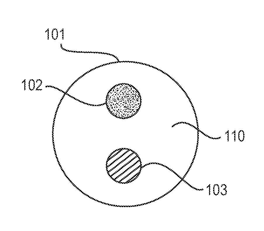
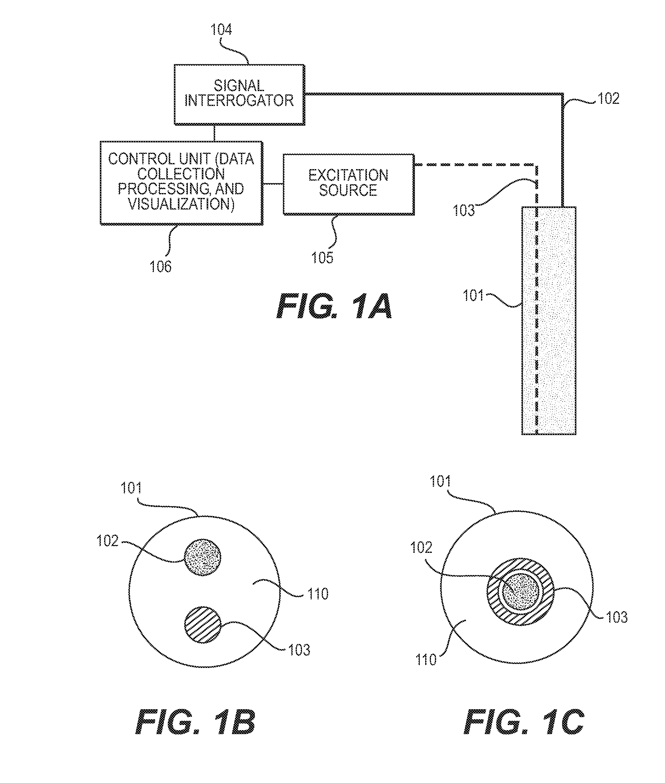
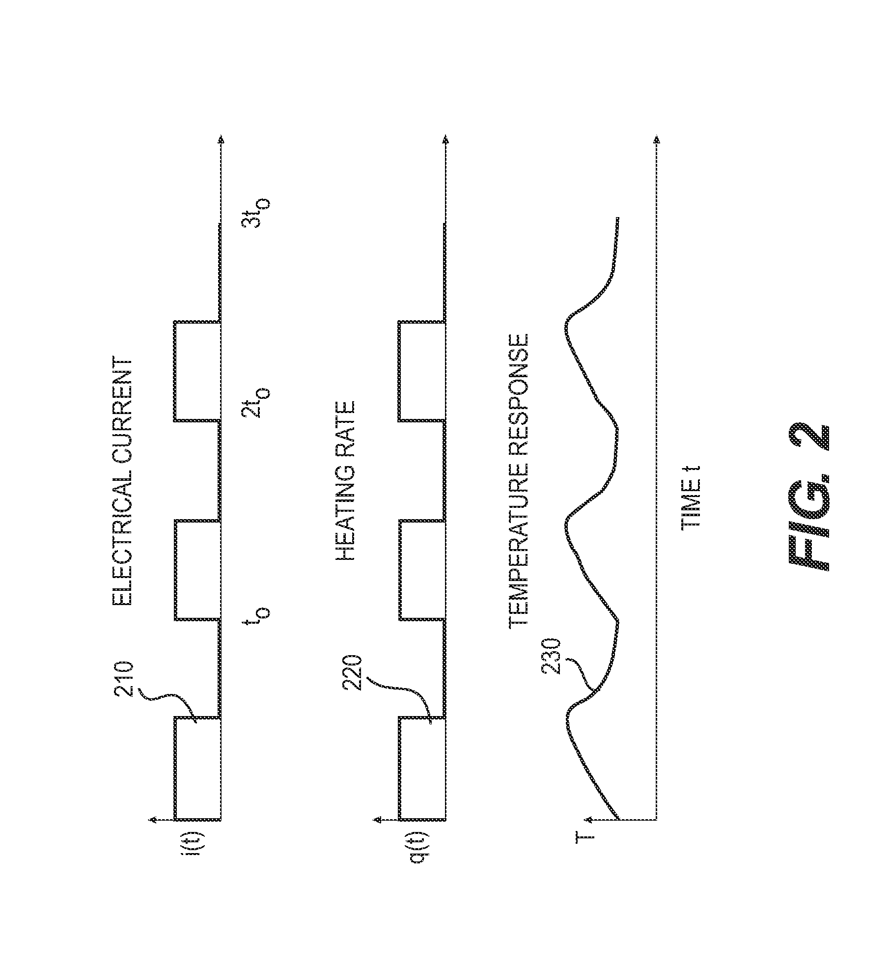
[0112]A method for detecting a leak in a pipeline, comprising: providing along a length of a perimeter of a wall of a pipeline a sensing cable including an optical fiber sensor array aligned with a heating element; propagating at least one heat pulse through the heating element along at least a portion of the sensing cable to affect an exchange of thermal energy between the heating element and fluid exposed to the sensing cable; measuring, over time, a temperature profile of the sensing cable corresponding to the heat pulse at each of a plurality of sensor locations on the optical fiber sensor array; and detecting a leak in a pipeline by determining one or more properties of the fluid exposed to the sensing cable at each of the plurality of sensor locations based on the temperature profile corresponding thereto.

embodiment 2

[0113]The method of any of the previous embodiments, wherein the sensing cable is provided along an axial length of the perimeter of the wall of the pipeline.

embodiment 3

[0114]The method of any of the previous embodiments, wherein the sensing cable further includes an outer diameter including a polymer sheath.


PUM


Abstract

System and method for detecting a leak in a pipeline with a sensing cable including an optical fiber sensor array aligned with a heating element. At least one heat pulse is propagated through the heating element along at least a portion of the sensing cable to affect an exchange of thermal energy between the heating element and fluid exposed to the sensing cable. A temperature profile of the sensing cable corresponding to the heat pulse at each of a plurality of sensor locations on the optical fiber sensor array is measured over time. A leak in a pipeline is detected by determining one or more properties of the fluid exposed to the sensing cable at each of the plurality of sensor locations based on the temperature profile corresponding thereto.

Description

CROSS-REFERENCE TO RELATED APPLICATIONS[0001]This application claims the benefit of U.S. Provisional Application Ser. Nos. 61 / 806,076, filed on Mar. 28, 2013, 61 / 806,107, filed on Mar. 28, 2013, 61 / 806,115, filed on Mar. 28, 2013, 61 / 919,870, filed on Dec. 3, 2013 and 61 / 919,949 filed on Dec. 3, 2013, each of which is incorporated by reference in its entirety herein, and from which priority is claimed.BACKGROUND[0002]1. Field[0003]The presently disclosed subject matter relates to methods and systems for detecting a leak in a pipeline. More particularly, the presently disclosed subject matter relates to detecting a leak in a pipeline using a sensing cable including an optical fiber sensor array aligned with a heating element.[0004]2. Description of Related Art[0005]Components of certain equipment, such as that used in the petroleum and petrochemical industry, which includes the exploration, production, refining, manufacture, supply, transport, formulation or blending of petroleum, pe...

Claims


Application Information

Patent Timeline
Patent Type & Authority Applications(United States)
IPC IPC(8): G01M3/04
CPCG01M3/04G01M3/002G01M3/165G01M3/38
Inventor KULKARNI, MOHAN G.ZHANG, YIBING
Owner EXXON RES & ENG CO
Why Eureka
Try Eureka