

Vibrator element and method of manufacturing the same
a technology of vibrator element and manufacturing method, which is applied in the direction of generator/motor, acceleration measurement using interia force, instruments, etc., can solve the problem of reducing the detection sensitivity of the vibrator elemen
- Summary
- Abstract
- Description
- Claims
- Application Information
AI Technical Summary
Benefits of technology
Problems solved by technology
Method used
Image

Examples
first embodiment
1. Configuration of Gyro Sensor which Includes Vibrator Element
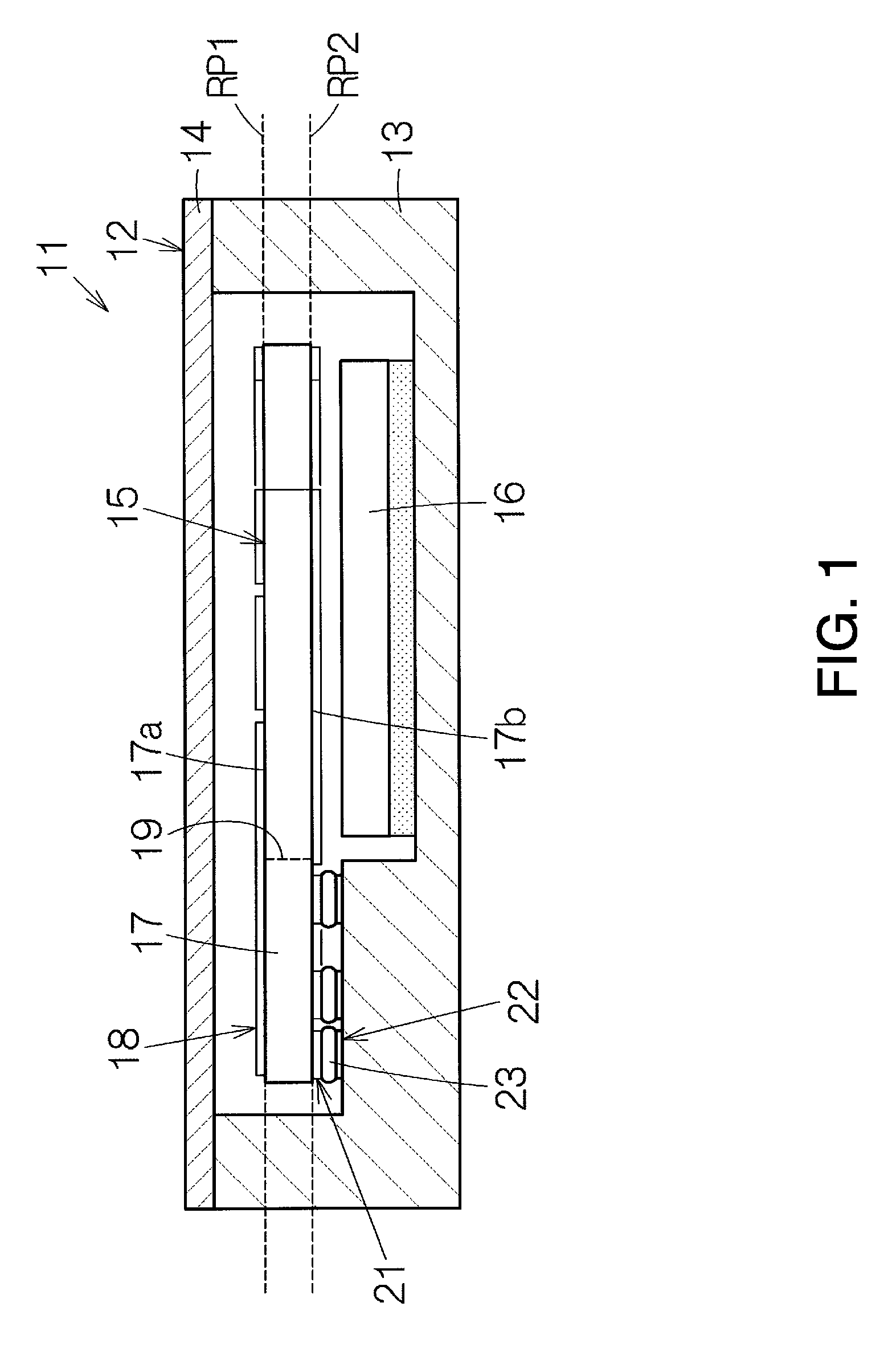
[0048]FIG. 1 schematically shows the configuration of a gyro sensor 11 according to an embodiment. The gyro sensor 11 is provided with a container 12 having, for example, a box shape. The container 12 is provided with a container main body 13 and a cover material 14. An opening of the container main body 13 is covered in an airtight manner with the cover material 14. An internal space of the container 12 can be sealed, for example, in a vacuum. The container 12 functions as a rigid body. At least the cover material 14 can be formed of a conductor. If the cover material 14 is grounded, the cover material 14 can exhibit a shielding effect with respect to electromagnetic waves.
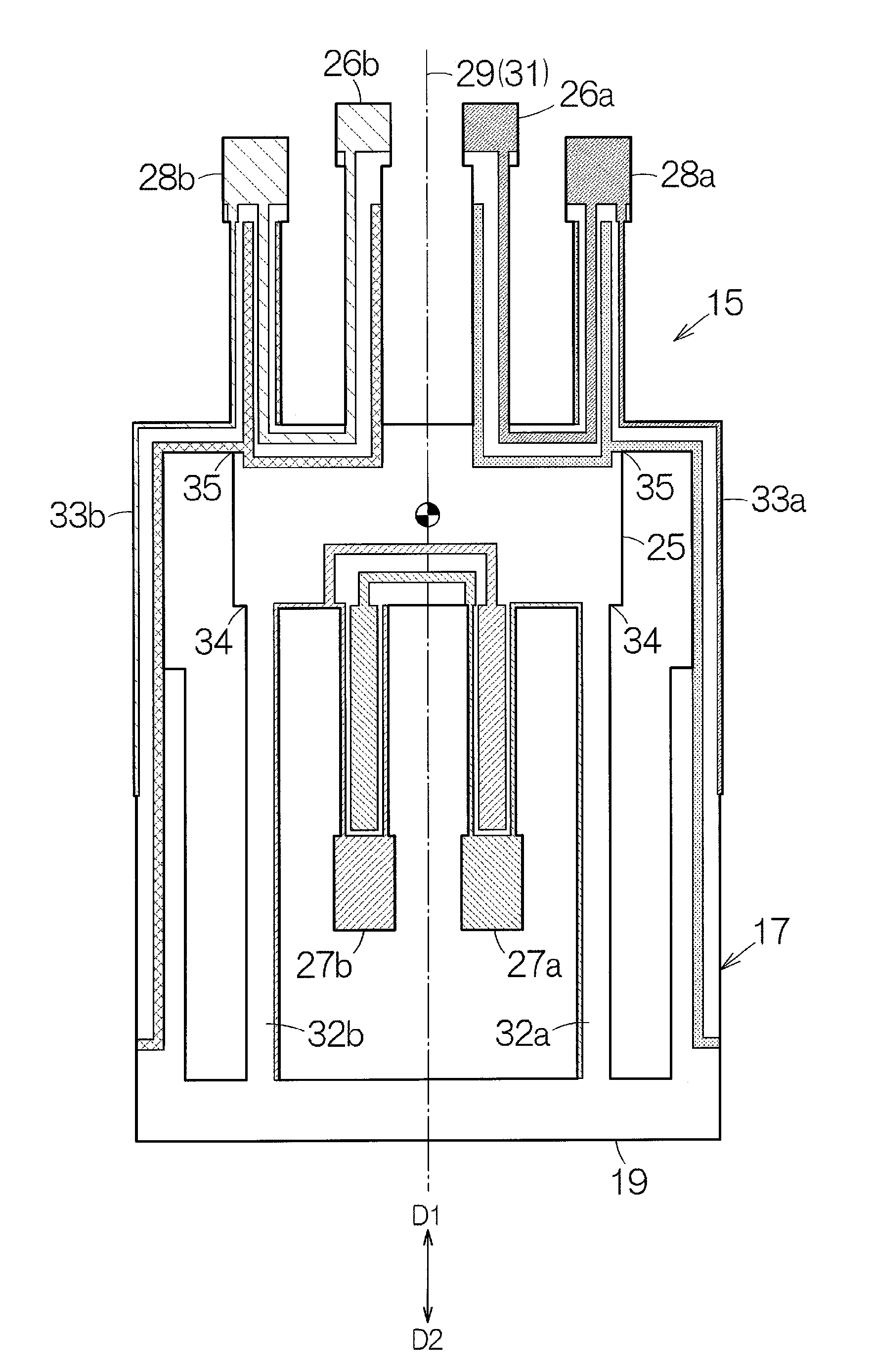
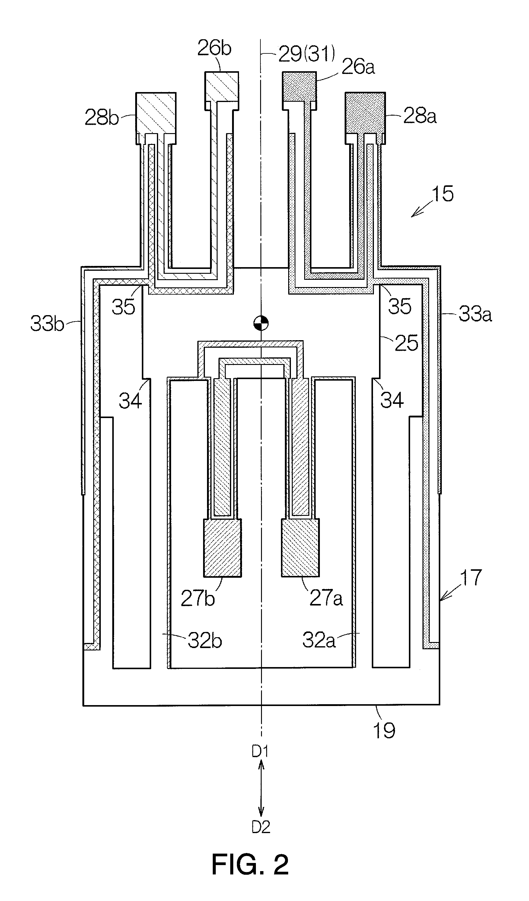
[0049]A vibrator element 15 and an integrated circuit (IC) chip 16 are accommodated in the container 12. The vibrator element 15 and the IC chip 16 are disposed in the internal space of the container 12. The vibrator element 15 is provided with a main...
second embodiment
5. Structure of Vibrator Element
[0086]FIG. 11 shows a portion of a vibrator element 15 according to a second embodiment. In the vibrator element 15, film bodies 63 are formed on the surfaces of the first vibrating arms 26a and 26b on the base portion 25 side. The film body 63 is formed of a metal material, for example, nickel. In addition, the film body 63 may be formed of an insulating material. However, in a case where the film body 63 is formed of a metal material, the film body 63 is electrically separated from the signal electrodes 47a and 48a and the ground electrodes 47b and 48b. The film bodies 63 are fixed to be superimposed on the surfaces of the first vibrating arms 26a and 26b. The film bodies 63 extend toward the free ends from the roots of the first vibrating arms 26a and 26b. The film body 63 may be continuous as far as the surface of the base portion 25. The film bodies 63 can increase rigidity at the roots of the first vibrating arms 26a and 26b. The size or the thi...
third embodiment
6. Structure of Vibrator Element
[0087]FIG. 12 shows a portion of a vibrator element 15b according to a third embodiment. In the vibrator element 15b, film bodies 64 are formed on the surfaces of the first vibrating arms 26a and 26b on the base portion 25 side. The film body 64 can be configured in the same manner as the film body 63. A removal mark 65 is formed adjacent to the film body 64 on the surface of each of the first vibrating arms 26a and 26b. The size of the removal mark 65 is determined according to an adjustment range of the required rigidity. Other configurations of the vibrator element 15b can be configured in the same manner as the vibrator element 15 of the first embodiment described above. In the vibrator element 15b, the ratio r of equivalent series resistance can be set to a predetermined value on the basis of the film body 64.
7. Method of Manufacturing Vibrator Element According to Third Embodiment
[0088]First, the vibrator element 15 according to the second embod...
PUM
| Property | Measurement | Unit |
|---|---|---|
| Electrical resistance | aaaaa | aaaaa |
| Ratio | aaaaa | aaaaa |
Abstract
Description
Claims
Application Information