Photovoltaic Module Mounting to Rubber Tires

a technology for photovoltaic modules and rubber tires, applied in the direction of heat collector mounting/support, lighting and heating apparatus, greenhouse gas reduction, etc., can solve the problems of high disassembly cost and inability to easily compact, and achieve the effect of reducing the peak force on the panel

Active Publication Date: 2014-10-02
ENERGY RELATED DEVICES
View PDF12 Cites 35 Cited by
  • Summary
  • Abstract
  • Description
  • Claims
  • Application Information

AI Technical Summary

Benefits of technology

[0007]The present invention utilizes one or more rubber tires as a mount for a photovoltaic panel. A means of securely gripping tire walls is accomplished through the use of a interposing the tire between a combination of plates, beams, bolts, rivets, harpoons, ratchets, or pins. This securing assembly holds the photovoltaic panel above the rubber tire. The rubber elastic mount performs as a shock mount, elastically distributing forces over time. This may reduce peak forces on the panel resulting from wind gusts, hail impacts, and vibrations incident on the mounting surface such as those caused by earthquakes or truck transport.

Problems solved by technology

In many areas of the world discarded rubber tires are major waste problem because they degrade very slowly in the environment, cannot be easily compacted into landfills, and are costly to disassemble due to structural toughness and complexity.

Method used


Image

  • Photovoltaic Module Mounting to Rubber Tires
  • Photovoltaic Module Mounting to Rubber Tires
  • Photovoltaic Module Mounting to Rubber Tires

Examples


Embodiment Construction

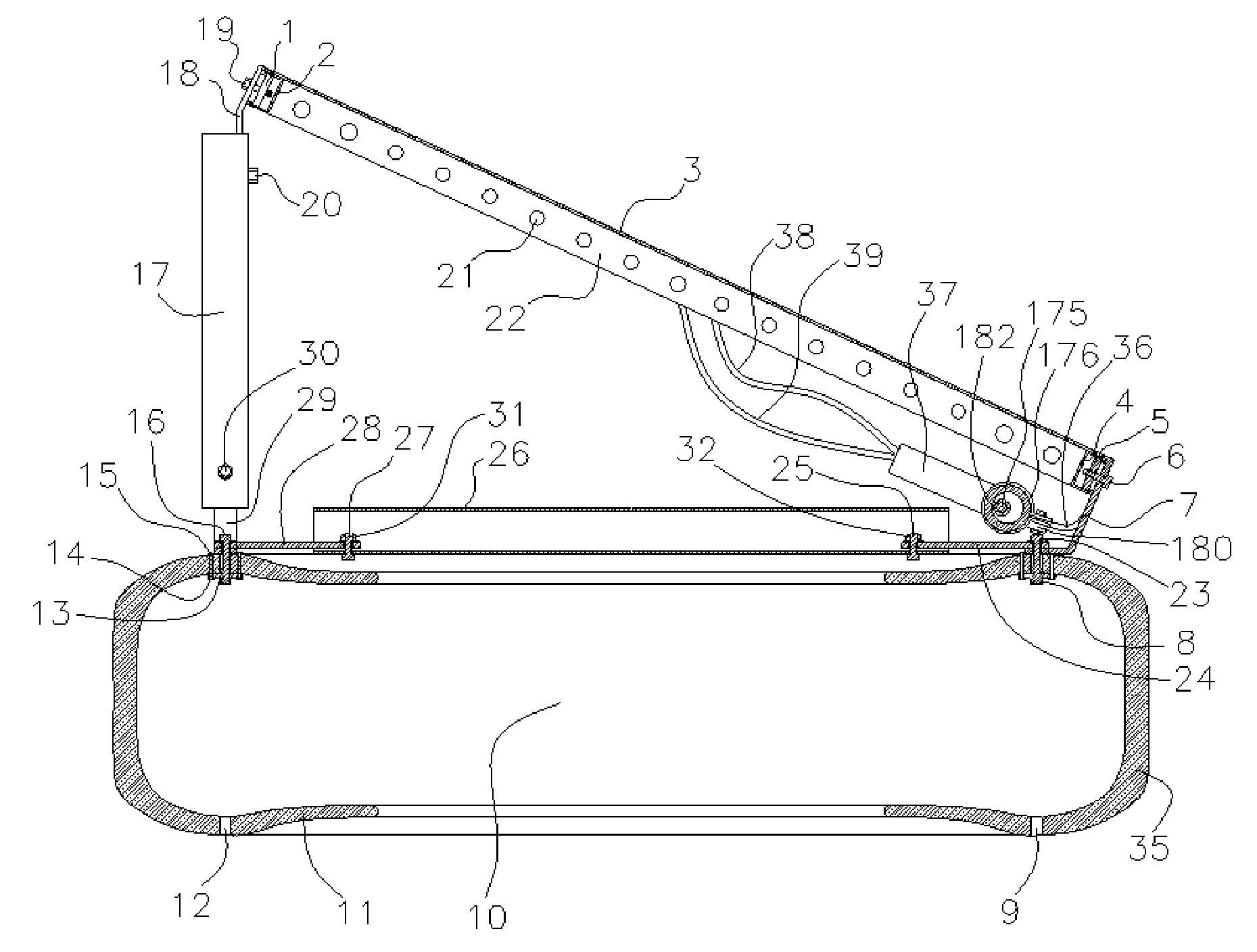
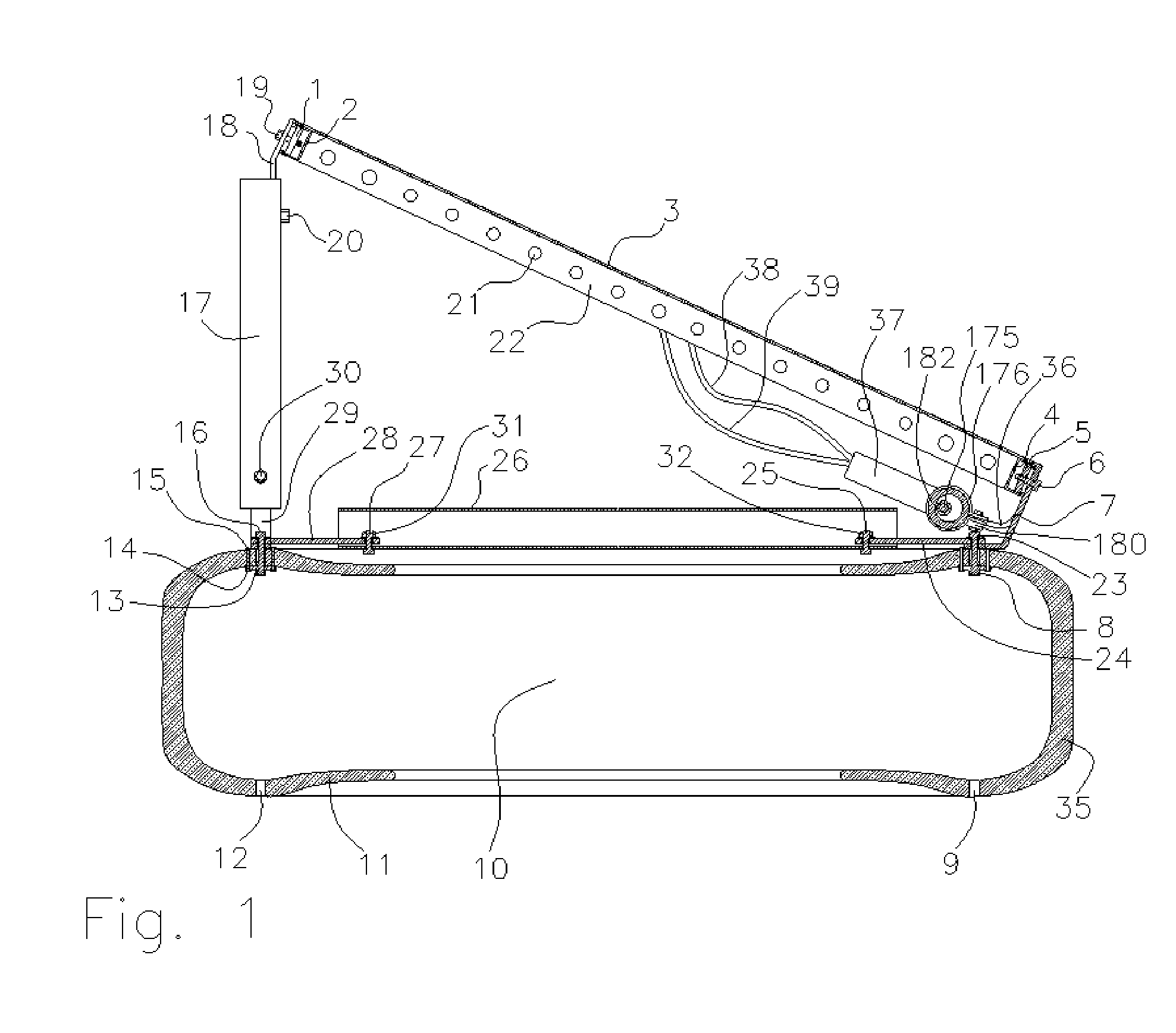
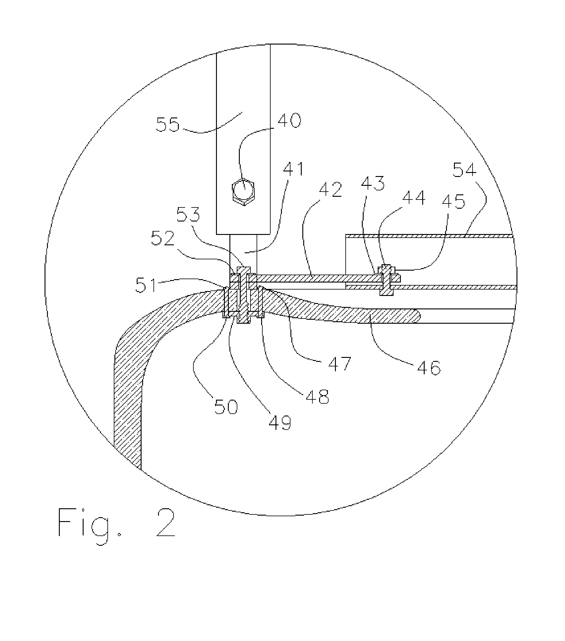
[0025]Several embodiments of the invention are illustrated with variations in assembly and arrangement. The following numbers identify elements within the drawings:

[0026]FIG. 1 Cross-sectional view of photovoltaic panel mounted to rubber tire.[0027]1. Sliding nut[0028]2. Channel beam (Unistrut)[0029]3. Photovoltaic panel glass and photovoltaic cells laminate[0030]4. Channel beam (Unistrut)[0031]5. Sliding nut[0032]6. Bolt[0033]7. Bent plate[0034]8. Hanger flange[0035]9. Drain hole[0036]10. Interior of tire[0037]11. Side wall of tire[0038]12. Drain hole[0039]13. Hanger flange[0040]14. Blind rivet expansion end[0041]15. Blind rivet flush head[0042]16. Bolt[0043]17. Metal tube[0044]18. Bent plate[0045]19. Bolt[0046]20. Nut[0047]21. Air flow holes in heat sink fin[0048]22. Back surface of photovoltaic heat sink fin[0049]23. Bolt[0050]24. Plate[0051]25. Bolt[0052]26. Cross-section of tube[0053]27. Bolt[0054]28. Plate[0055]29. Bent plate[0056]30. Nut[0057]31. Nut[0058]32. Nut[0059]33. Glu...


PUM

PropertyMeasurementUnit
wind speedsaaaaaaaaaa
temperatureaaaaaaaaaa
voltagesaaaaaaaaaa

Abstract

A photovoltaic panel mounting system utilizes rubber tires to anchor and position photovoltaic panels to face the sun and resist wind forces. The shaded interior cavity of the rubber tires physically and thermally protects electronics and batteries. The tires may be filled with soil, concrete, water, or aggregate to provide further ballasting, enabling a photovoltaic mount system to withstand high velocity winds. Telescoping conduits may house wiring for the system and allow for resizing and reshaping of the mounting system. The mounting system decreases used tire waste and provides low cost components and portability.

Description

[0001]This application claims the benefit of U.S. Provisional Application No. 61 / 807,422, filed Apr. 2, 2013, which is hereby incorporated by reference in its entirety.BACKGROUND OF THE INVENTION[0002]Photovoltaic module systems require a mounting system to be used need be held to face the sun and resist the forces created by wind, rain, hail, and snow. Conventional mounting rack systems utilize a rack that clamps the photovoltaic panel or modules by the edge or edge frame. The rack is then attached to beams to the mounting surface such as a roof, wall, or ground. The attachment can be through screws into the mount surface, such as ground screws into the ground, wood screws into roof joists, or bolts and nuts into steel beam roofs. The rack can also be held against the mounting surface by gravity by weighting the rack with concrete weights. Pilings or cast concrete have also been used to hold racks to the ground.[0003]These mounting systems are expensive because they use a high quan...

Claims


Application Information

Patent Timeline
Patent Type & Authority Applications(United States)
IPC IPC(8): H01L31/042B29C65/70
CPCB29C65/70H01L31/0422F24S25/11F24S25/13F24S25/617F24S2025/802F24S2080/015H02S20/00H02S20/10H02S20/30H02S40/38Y02B10/10Y02B10/20Y02E10/47Y02E10/50Y02E70/30
Inventor HOCKADAY, ROBERT G.
Owner ENERGY RELATED DEVICES
Why Eureka
Try Eureka