Plasma wavguide using step part and block part

a technology of step parts and waveguides, which is applied in the direction of waveguides, structural circuit elements, waveguide type devices, etc., can solve the problems of high-cost sealing apparatus separately required, difficulty in fine tuning of microwave oscillators from magnetrons, and leakage of weak electromagnetic fields out of waveguides

Active Publication Date: 2014-10-02
TRIPLE CORES TECH CO LTD
View PDF16 Cites 14 Cited by
  • Summary
  • Abstract
  • Description
  • Claims
  • Application Information

AI Technical Summary

Benefits of technology

[0014]It is thus an object of the present disclosure to provide a novel plasma waveguide system with improved economic and technical efficiency.
[0020]The present disclosure forms a step part having a height decreasing to a predetermined level within a waveguide, and provides a block part of a predetermined height at an inner side surface of the waveguide opposite to the step part of the waveguide. Thereby, a problem with microwave leaks involved in a 3-stub system penetrating through an overall waveguide and a problem with damage to an external system due to microwaves traveling outward may be effectively solved. Further, because the block part of the predetermined height provided at the inner side surface of the waveguide is located at an opposite surface to the step part, an effect of microwave concentration within the waveguide having a gradual reduction in height in a microwave propagation direction may be maximized.

Problems solved by technology

However, in this case, there is a problem—fine tuning of microwaves oscillated from a magnetron is difficult.
Also, by a structure of the 3-stub matching system penetrating through the waveguide, leaks of a weak electromagnetic field out of the waveguide and its resultant arcing occur.
To solve this problem, a high-cost sealing apparatus is separately required to prevent an electromagnetic field from leaking out of the waveguide.

Method used


Image

  • Plasma wavguide using step part and block part
  • Plasma wavguide using step part and block part
  • Plasma wavguide using step part and block part

Examples


Embodiment Construction

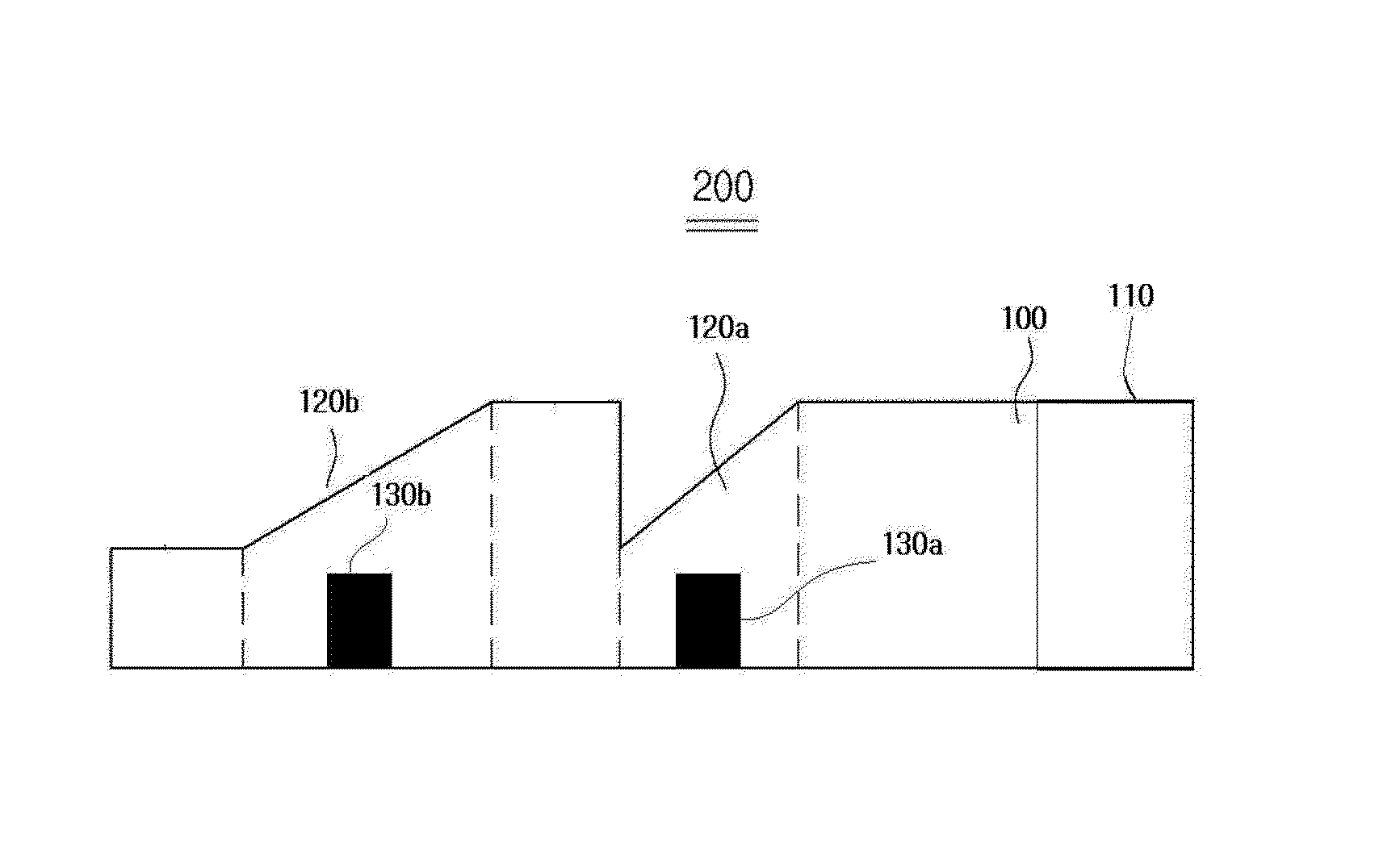
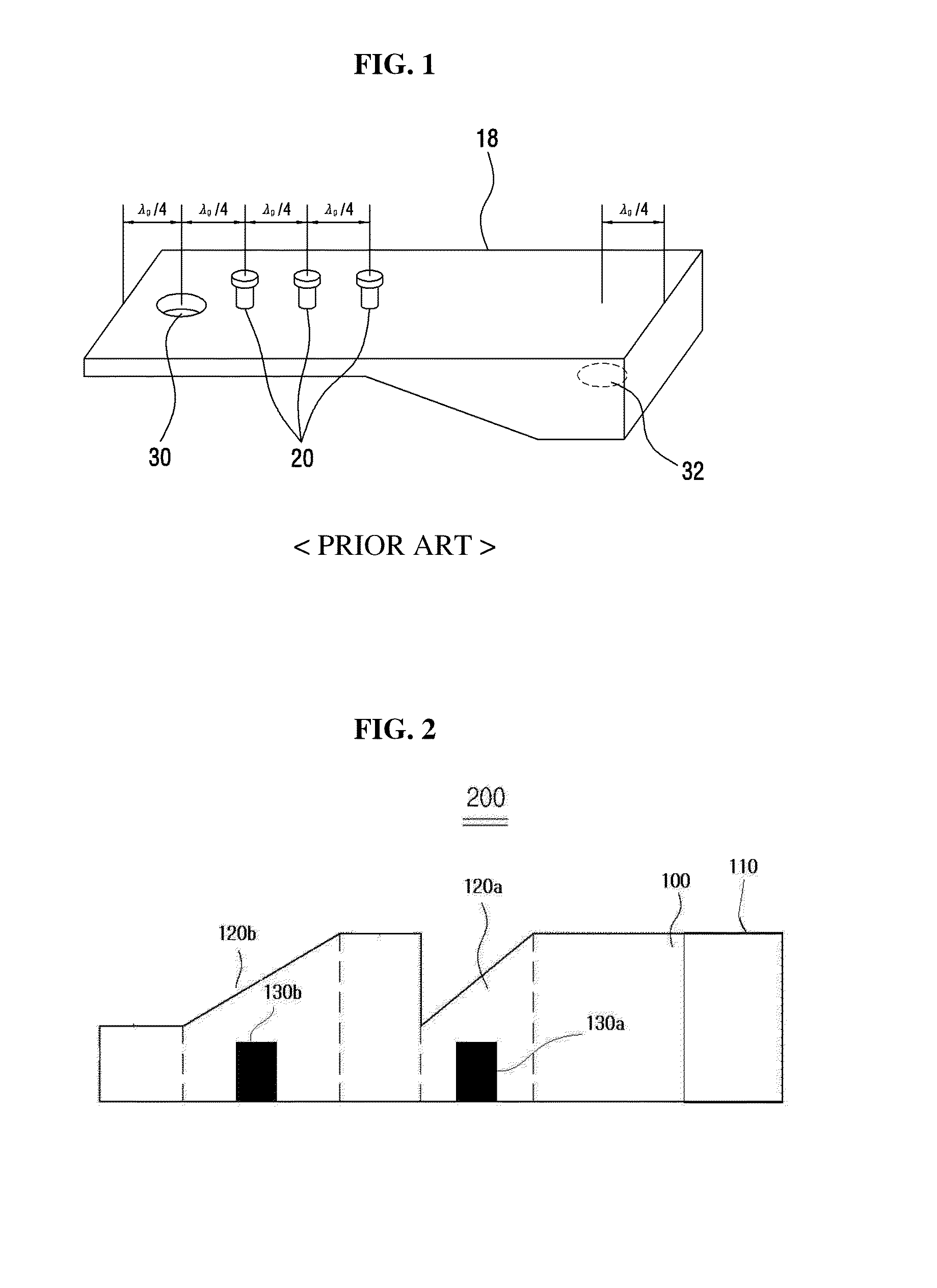
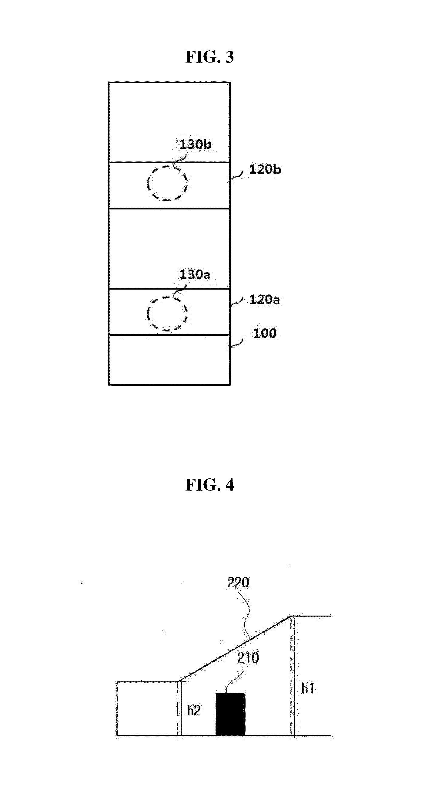
[0029]The present disclosure now will be described more fully hereinafter with reference to the accompanying drawings, in which embodiments of the invention are shown. This invention may, however, be embodied in many different forms and should not be construed as limited to the embodiments set forth herein. Rather, these embodiments are provided so that this disclosure will be thorough and complete, and will fully convey the scope of the invention to those skilled in the art. In addition, when the elements of each of the figures are denoted by reference numerals, it should be noted that like elements are denoted by like reference numerals although illustrated in different figures. In addition, in the description of the present disclosure, details of well-known configurations or functions may be omitted to avoid unnecessary obscuring the gist of the present disclosure.

[0030]The terminology used herein is for the purpose of describing particular embodiments only and is not intended to...


PUM


Abstract

In a magnetron and a plasma waveguide through which a microwave oscillated from the magnetron moves, there is provided a plasma waveguide including a plurality of step parts formed at any one side on an inner side surface of the waveguide, and a block part of a predetermined height formed at any other side on the inner side surface of the waveguide, wherein the block part is formed at a side opposite to a boundary part between the plurality of step parts.

Description

CROSS-REFERENCE TO RELATED APPLICATION[0001]This application claims priority of Korean Patent Application No. 10-2013-0032748, filed on Mar. 27, 2013, in the KIPO (Korean Intellectual Property Office), the disclosure of which is incorporated herein entirely by reference.BACKGROUND OF THE INVENTION[0002]1. Field of the Invention[0003]The present disclosure relates to a plasma waveguide using a step part and a block part, and more particularly, to a plasma waveguide using a step part and a block part that may produce an effect of microwave matching while maximizing an effect of microwave concentration within the waveguide having a gradual reduction in height in a microwave propagation direction by using the step part simultaneously with the block part of a predetermined height provided at an inner side surface of the waveguide.[0004]2. Description of the Related Art[0005]A conventional plasma generator includes a waveguide to transmit electromagnetic waves, a 3-stub to tune a plasma i...

Claims


Application Information

Patent Timeline
Patent Type & Authority Applications(United States)
IPC IPC(8): H01J37/32H03H7/38
CPCH03H7/38H01J37/32229H01P5/024H05H1/46H05H1/4622H01P3/123
Inventor KIM, IK NYUNKANG, SUNG OKEUM, MIN HEUM
Owner TRIPLE CORES TECH CO LTD
Why Eureka
Try Eureka