Ac LED lighting apparatus

a technology of led lighting and led light, which is applied in the direction of lighting and heating apparatus, semiconductor devices for light sources, planar light sources, etc., can solve the problems of increasing manufacturing costs, inefficiency in adjustment of the number of leds constituting each light emitting group, and complicated circuit design of lighting apparatuses. achieve maximum luminous efficacy, uniform illumination, and maximum luminous efficacy

Inactive Publication Date: 2014-10-02
GLOW ONE CO LTD
View PDF9 Cites 28 Cited by
  • Summary
  • Abstract
  • Description
  • Claims
  • Application Information

AI Technical Summary

Benefits of technology

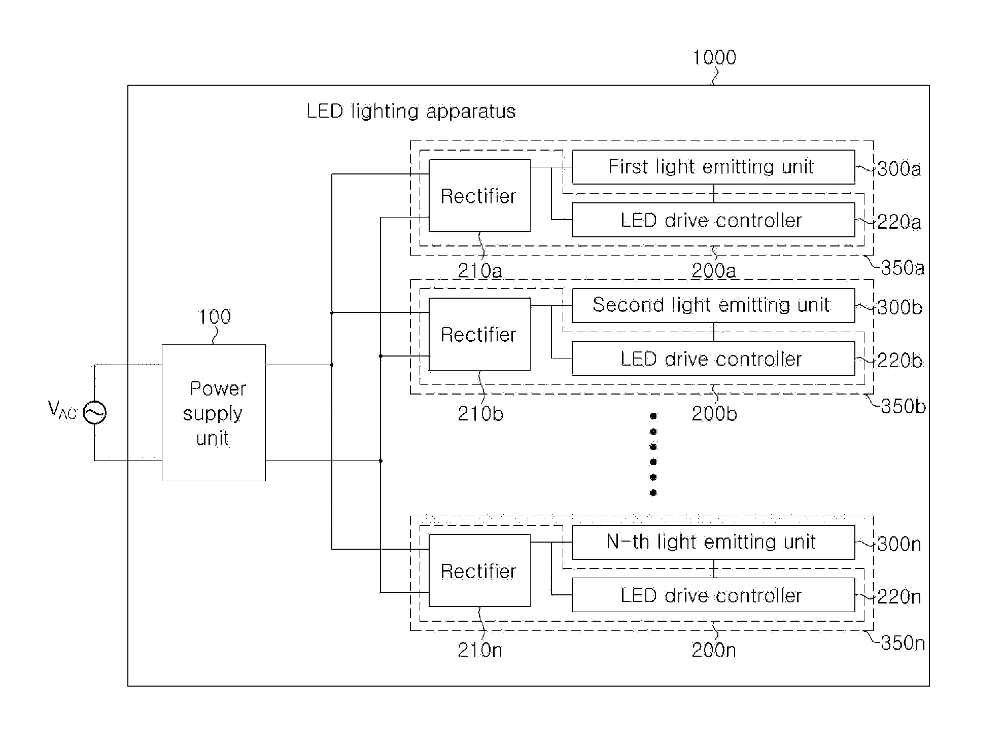
[0040]As described above, according to embodiments of the invention, the sequential drive type LED lighting apparatus may have maximum luminous efficacy and uniform illumination by disposing a plurality of lighting blocks in an optimal arrangement.
[0041]In addition, accor

Problems solved by technology

As a result, a light emitting device employing such a conventional light emitting diode is limited in applicability and requires a separate circuit such as an SMPS when used in domestic settings employing AC power, thereby complicated circuit design of a lighting apparatus while increasing manufacturing costs.
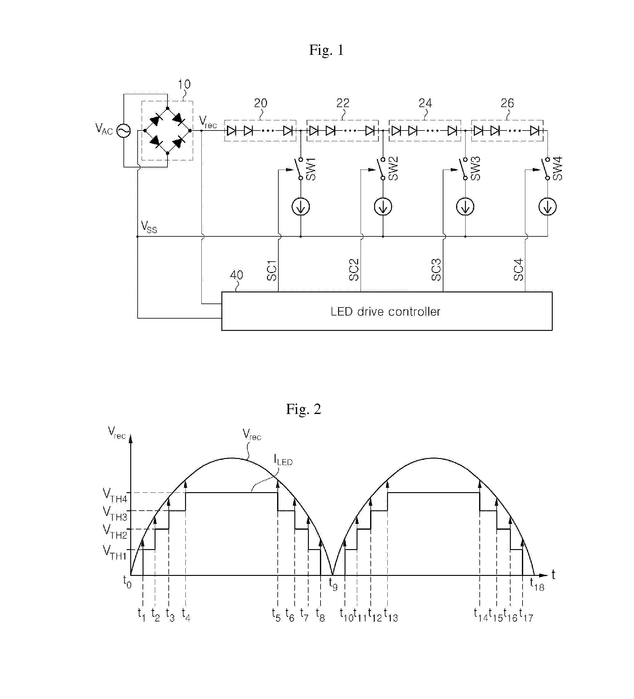
In such a conventional AC LED lighting apparatus as shown in FIG. 1, although luminous flux can be regulated by adjusting the number of LEDs constituting each of the light emitting groups in the LED lighting apparatus, there can be a problem of inefficiency in adjustment of the number of LEDs constituting each of the light emitting groups.
In other words, although the number of LEDs in each of the light emitting groups can be increased to increase luminous flux of the LED lighting apparatus, the number of LEDs to be added to the LED lighting apparatus may be limited due to physical limitations (such as a maximum value of the is rectified voltage Vrec, a forward voltage level of the light emitting groups, the number of LEDs to be included in the LED lighting apparatus, manufacturing costs, and the like).
However, conventional techniques do not pro

Method used


Image

  • Ac LED lighting apparatus
  • Ac LED lighting apparatus
  • Ac LED lighting apparatus

Examples


fifth embodiment

[0100]FIG. 10 is a detailed layout diagram of light emitting groups in light emitting blocks according to a fifth exemplary embodiment of the invention. Unlike the LED arrangement of FIG. 5 wherein the LED are disposed in the first to fourth rows, in the LED arrangement shown in FIG. 10, fourteen LEDs are disposed in a zigzag arrangement from the periphery of the circuit board 400 towards the center thereof. Note that lines connecting the LEDs to each other in the drawings are imaginary lines for explaining the zigzag arrangement of the LEDs rather than the connection relationship between the LEDs.

[0101]In the LED arrangement according to the fifth exemplary embodiment of FIG. 10, LEDs are disposed in the zigzag arrangement from the periphery of the circuit board 400 towards the center of the circuit board circuit board 400 to be grouped into first to fourth light emitting groups 310 to 340, such that the first light emitting group 310 to the fourth light emitting group 340 are seq...

sixth embodiment

[0103]FIG. 11 is a detailed layout diagram of light emitting groups in light emitting blocks according to a sixth exemplary embodiment of the invention. In FIG. 11, although LEDs are arranged in a similar manner to the LED arrangement according to the embodiment shown in FIG. 10, the LEDs are grouped in reverse order to the LED arrangement of the embodiment of FIG. 10. Thus, an LED placed at a location most adjacent to the center of the circuit board 400 is designated as a first LED (LED 1), and an LED placed at the outermost side of the circuit board 400 along an imaginary zigzag line is designated as a fourteenth LED (LED 14). Accordingly, in the LED arrangement according to this embodiment of FIG. 11, the first to fourth light emitting groups 310 to 340 arranged in the zigzag manner are sequentially turned on from the center of the circuit board 400 towards the periphery thereof as the voltage level of the rectified voltage Vrec increases, and the fourth light emitting group 340 ...


PUM


Abstract

Embodiments of the invention provide AC LED lighting apparatuses. The AC LED lighting apparatuses may increase luminous flux and provide optimal efficiency through novel arrangement of a plurality of light emitting blocks on a circuit board and a plurality of LEDs and drive ICs included in each of the light emitting blocks to be sequentially driven, and/or through efficient series-parallel connection between a limited number of LEDs.

Description

CROSS-REFERENCE TO RELATED APPLICATIONS[0001]This application claims priority from and the benefit of Korean Patent Application No. 10-2013-0034330, filed on Mar. 29, 2013, and Korean Patent Application No. 10-2013-0034331, filed on Mar. 29, 2013, which are hereby incorporated by reference for all purposes as if fully set forth herein.BACKGROUND OF THE INVENTION[0002]1. Field of the Invention[0003]Embodiments of the invention relate to light emitting diode (LED) lighting apparatuses driven by AC power, and more particularly, to AC LED lighting apparatuses that may increase luminous flux with optimal efficiency through optimal arrangement of a plurality of light emitting blocks on a circuit board and a plurality of LEDs and drive ICs included in each is of the light emitting blocks to be sequentially driven, and / or through efficient series-parallel connection between a limited number of LEDs.[0004]2. Discussion of the Background[0005]Generally, a light emitting diode package includes...

Claims


Application Information

Patent Timeline
IPC IPC(8): H05B33/08H05B44/00
CPCH05B33/0821F21K9/00F21Y2105/10F21Y2115/10H01L25/0753H05K1/111H05K2201/09227H05K2201/10106H05B45/44H05B45/40H05B45/30H05B47/155H05B41/3927
Inventor YOON, SEONG BOKYANG, HWI SEOKKIM, CHUL JU
Owner GLOW ONE CO LTD
Why Eureka
Try Eureka