
Testing Integrated Circuit Packaging for Output Short Circuit Current

a technology of integrated circuits and output short circuit current, which is applied in the direction of electrical testing, measurement devices, instruments, etc., can solve the problems of registering a substantial increase in current measurement at the output pin, and taking a significant amount of test tim

Active Publication Date: 2014-10-02
TEXAS INSTR INC
View PDF14 Cites 3 Cited by
  • Summary
  • Abstract
  • Description
  • Claims
  • Application Information

AI Technical Summary

Benefits of technology

The invention relates to testing integrated circuits, particularly those with a large number of output pins. The invention provides a method for testing output short circuit current (IOS) in parallel, which is important for ensuring the integrity of the device's output protective circuit in the event of a short on the output pins. The method uses automatic test equipment (ATE) with high-speed digital (HSD) pins for functional testing of a logic circuit. The invention also discusses a chip scale package (CSP) and wafer-level chip-scale package (WL-CSP) which are types of integrated circuit packaging. The technical effects of the invention include reducing testing time and ensuring efficient and reliable testing of output short circuit current in parallel.

Problems solved by technology

High density devices with high output pin count may have a large number of output pins that may require output short circuit current (IOS) testing.
If, however, there is a defect in the current protective circuit and the current limiting failed, a huge amount of current may flow out from the device and thus register a substantial increase in current measurement at the output pin.
Due to the tester current measuring resources capability and availability limitation in ATE environment, IOS testing is commonly performed serially pin by pin, which takes a significant amount of test time.

Method used


Image

  • Testing Integrated Circuit Packaging for Output Short Circuit Current
  • Testing Integrated Circuit Packaging for Output Short Circuit Current
  • Testing Integrated Circuit Packaging for Output Short Circuit Current

Examples


Embodiment Construction

[0013]Specific embodiments of the invention will now be described in detail with reference to the accompanying figures. Like elements in the various figures are denoted by like reference numerals for consistency. In the following detailed description of embodiments of the invention, numerous specific details are set forth in order to provide a more thorough understanding of the invention. However, it will be apparent to one of ordinary skill in the art that the invention may be practiced without these specific details. In other instances, well-known features have not been described in detail to avoid unnecessarily complicating the description.

[0014]Automatic test equipment (ATE) used for mixed signal or digital device testing in the semiconductor industry commonly has a large number of high speed digital (HSD) pins for digital functionality testing. An HSD tester is a highly parallel testing instrument that is configured to perform tests for multiple pins simultaneously and is typic...


PUM


Abstract

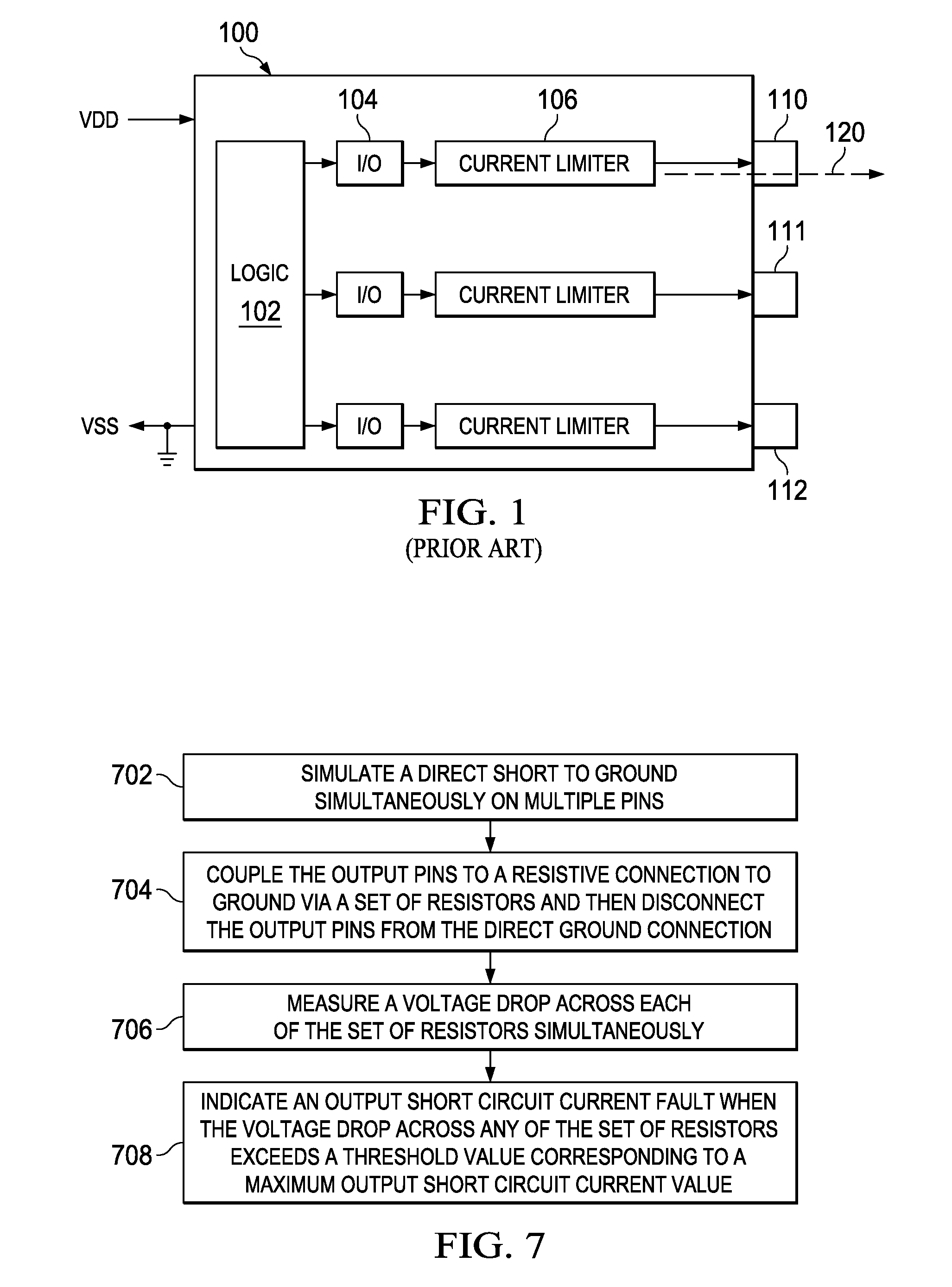
An electronic package having multiple pins may be tested in parallel for output short circuit current by simulating a direct short to ground by simultaneously connecting multiple output pins directly to ground in order to active a current limiter associated with each of the output pins. The pins are then connected to a resistive connection to ground via a set of resistors; the direct ground is then removed, such that the current limiter associated with each of the output pins remains activated. A voltage drop across each of the set of resistors is measured simultaneously. An output short circuit current fault is indicated when the voltage drop across any of the resistors exceeds a threshold value corresponding to a maximum output short circuit current value

Description

FIELD OF THE INVENTION[0001]This invention generally relates to testing packaged integrated circuits, and particular to testing a large number of pins for output short circuit current in parallel.BACKGROUND OF THE INVENTION[0002]As the performance and complexity of integrated circuits (IC) has increased over the years, the number of input / output (I / O) pin count has also increased significantly. High density devices with high output pin count may have a large number of output pins that may require output short circuit current (IOS) testing. It is a common practice to perform output IOS testing in order to verify the integrity of a device output protective circuit in the event of short on the output pins. IOS test simulate the worst-case loading conditions on the output pin of a device. The test guarantees that whenever output current exceeds the trip point for the IOS detection in the event of a short, the current limiting block would kick in to prevent the device from exceeding its ...

Claims


Application Information

Patent Timeline
Patent Type & Authority Applications(United States)
IPC IPC(8): G01R31/02
CPCG01R31/025G01R31/31715
Inventor ONG, CHEE PENGWOON, WEN HUIZHANG, BENYONGLINDGREN, ERIC
Owner TEXAS INSTR INC
Learn More