Display device and electronic apparatus
- Summary
- Abstract
- Description
- Claims
- Application Information
AI Technical Summary
Benefits of technology
Problems solved by technology
Method used
Image

Examples
first embodiment
2. First Embodiment
First Embodiment
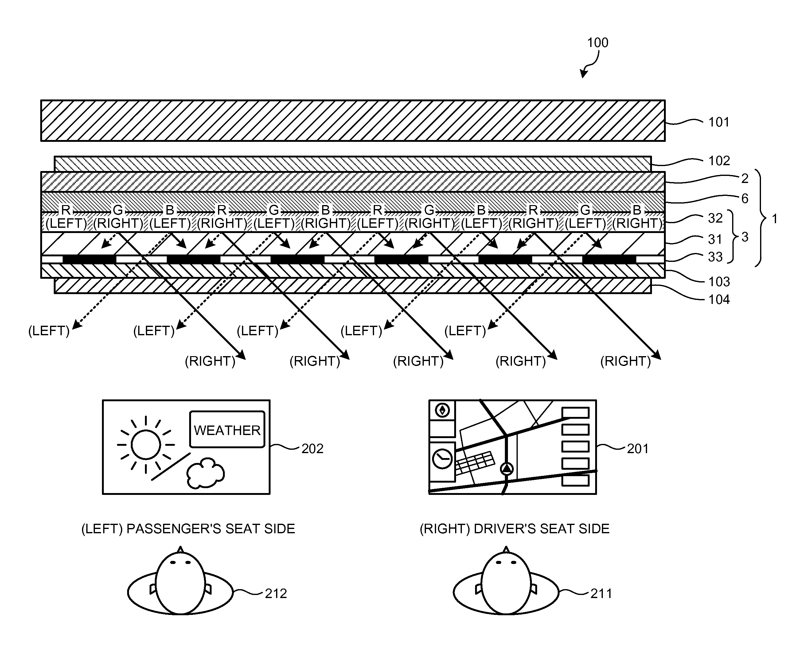
[0124]FIG. 18 is a cross-sectional view illustrating a display panel according to a first embodiment. FIG. 18 illustrates four adjacent pixels of the display panel 1 according to the first embodiment. From the right side to the left side in FIG. 18, the blue (B) pixel Vpix(B1), the green (G) pixel Vpix(G), the red (R) pixel Vpix(R), and the blue (B) pixel Vpix(B2) are positioned. The pixel Vpix(B1) and the pixel Vpix(G) are adjacent to each other. The pixel Vpix(G) and the pixel Vpix(R) are adjacent to each other. The pixel Vpix(R) and the pixel Vpix(B2) are adjacent to each other. Each of the pixels Vpix(B1), Vpix(G), Vpix(R), and Vpix(B2) includes the pixel electrode 27 on the front surface of the TFT substrate 2 (on the surface on the side of the counter substrate 3).
[0125]The liquid crystal 6 modulates light passing therethrough, depending on a state of an electric field between the pixel electrode 27 and the common electrode VCOM (see FIG. 5)....
first modification
of First Embodiment
[0142]In the first embodiment, an opening is provided on a black matrix to increase the black luminance. However, the black matrix may be formed as a thin film or may be made of a material with high light transmission, in order to increase the black luminance.
[0143]FIG. 21 is a cross-sectional view illustrating a display panel according to a first modification of the first embodiment. FIG. 21 illustrates four adjacent pixels of the display panel 1 according to the first modification. From the right side to the left side in FIG. 21, the blue (B) pixel Vpix(B1), the green (G) pixel Vpix(G), the red (R) pixel Vpix(R), and the blue (B) pixel Vpix(B2) are positioned. The pixel Vpix(B1) and the pixel Vpix(G) are adjacent to each other. The pixel Vpix(G) and the pixel Vpix(R) are adjacent to each other. The pixel Vpix(R) and the pixel Vpix(B2) are adjacent to each other. Each of the pixels Vpix(B1), Vpix(G), Vpix(R), and Vpix(B2) includes the pixel electrode 27 on the fr...
second modification
of First Embodiment
[0159]In the first embodiment, an opening is provided on a black matrix to increase the black luminance. In the first modification of the first embodiment, a black matrix is formed as a thin film or made of a material with high light transmission to increase the black luminance. The black luminance can be further increased by forming no color filter underneath the black matrix.
[0160]FIG. 22 is a cross-sectional view illustrating a display panel according to a second modification of the first embodiment. FIG. 22 illustrates four adjacent pixels of the display panel 1 according to the second modification. From the right side to the left side in FIG. 22, the blue (B) pixel Vpix(B1), the green (G) pixel Vpix(G), the red (R) pixel Vpix(R), and the blue (B) pixel Vpix(B2) are positioned. The pixel Vpix(B1) and the pixel Vpix(G) are adjacent to each other. The pixel Vpix(G) and the pixel Vpix(R) are adjacent to each other. The pixel Vpix(R) and the pixel Vpix(B2) are adj...
PUM
 Abstract
Description
Claims
Application Information
 - Generate Ideas
- Intellectual Property
- Life Sciences
- Materials
- Tech Scout
- Unparalleled Data Quality
- Higher Quality Content
- 60% Fewer Hallucinations
Browse by: Latest US Patents, China's latest patents, Technical Efficacy Thesaurus, Application Domain, Technology Topic, Popular Technical Reports.
© 2025 PatSnap. All rights reserved.Legal|Privacy policy|Modern Slavery Act Transparency Statement|Sitemap|About US| Contact US: help@patsnap.com