

Optical element, window material, fitting, solar shading device, and building
a technology for solar shading and optical elements, applied in the direction of mirrors, instruments, constructions, etc., can solve problems such as the degradation of film visibility, and achieve the effect of suppressing the generation of irregular thickness of stripe-like films
Active Publication Date: 2014-10-02
DEXERIALS CORP
View PDF6 Cites 41 Cited by
- Summary
- Abstract
- Description
- Claims
- Application Information
AI Technical Summary
Benefits of technology
The technical effect of this patent is to provide optical elements, window materials, fittings, solar shading devices, and buildings that can prevent the formation of uneven stripes when the film thickness is measured.
Problems solved by technology
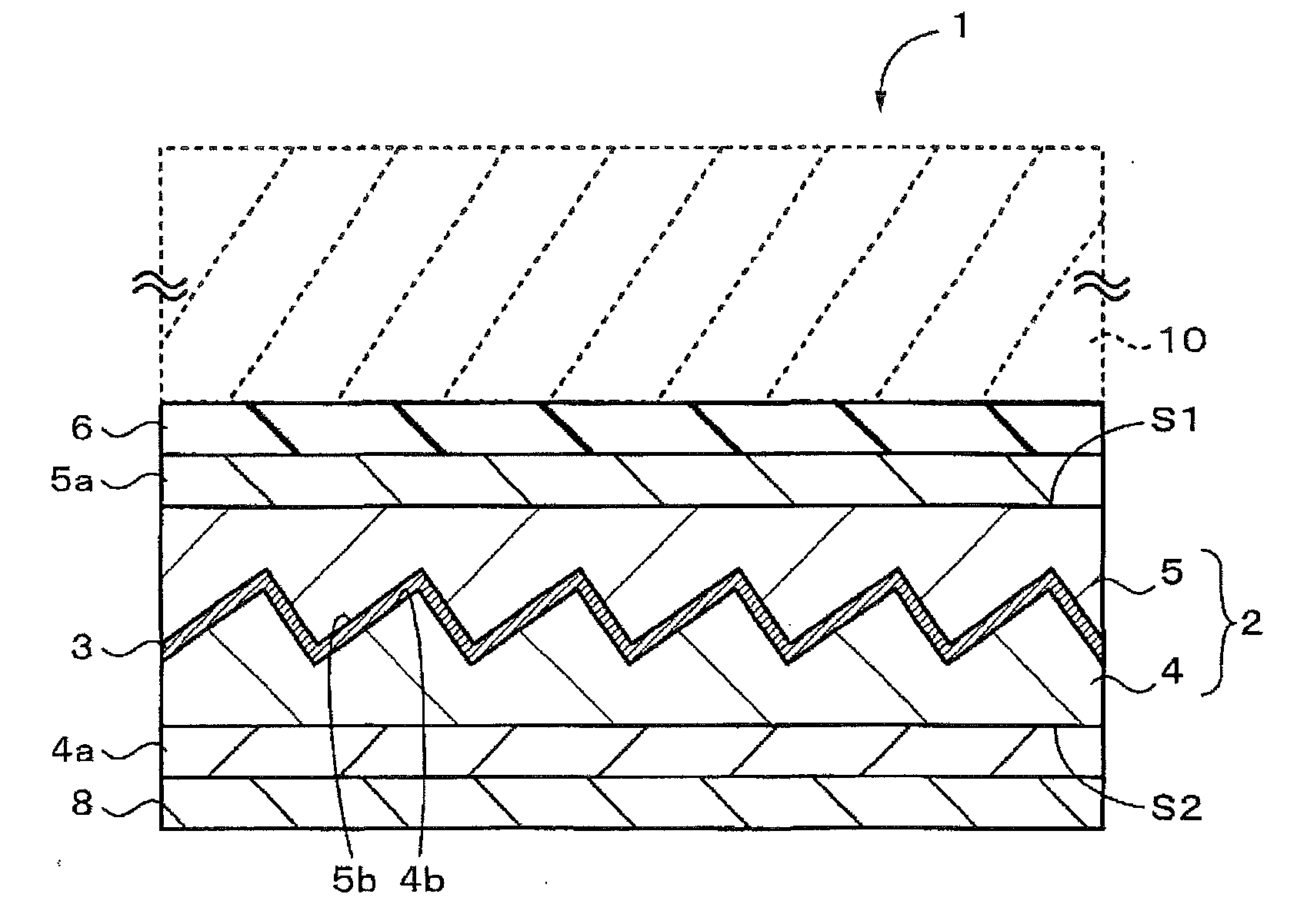
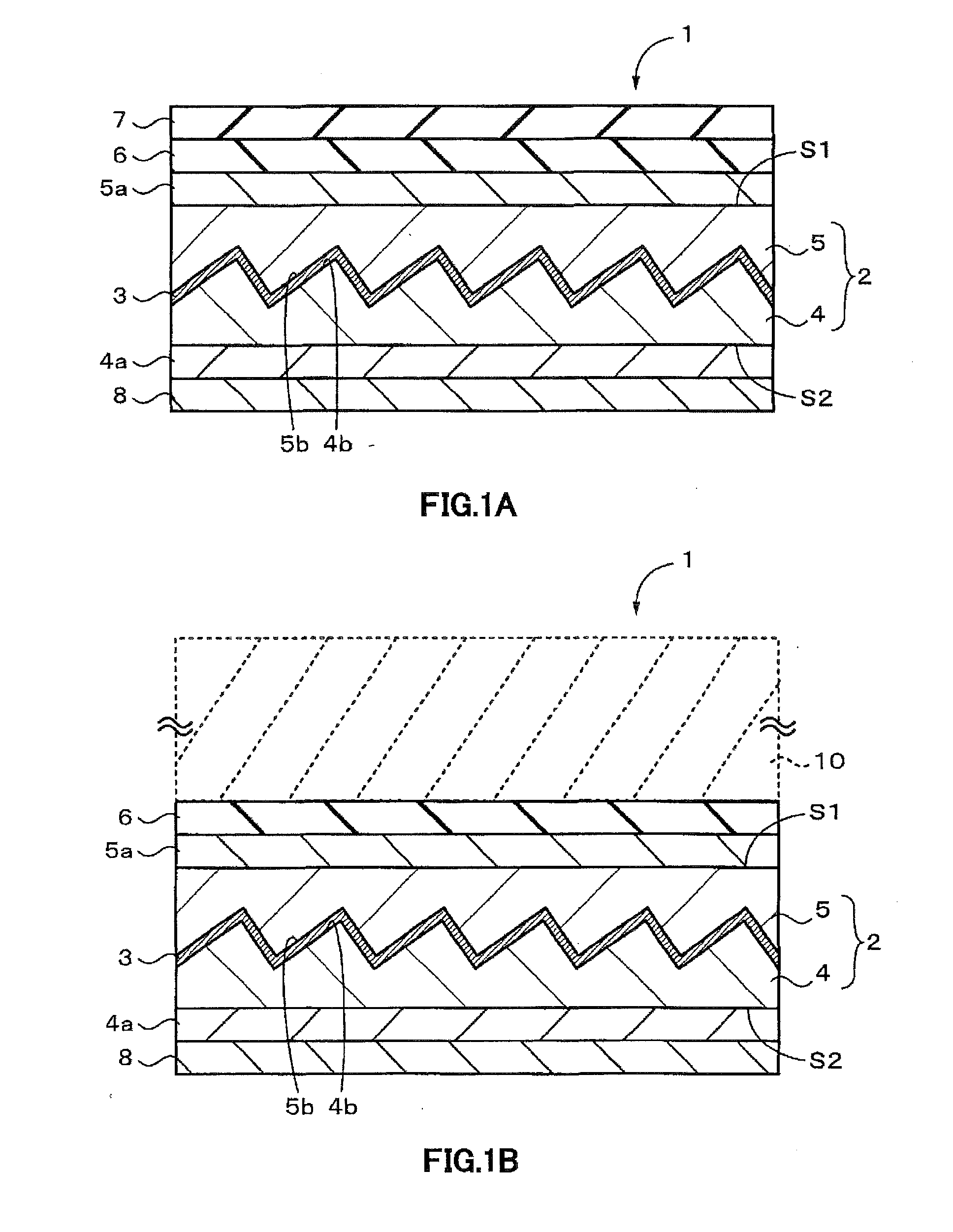
However, in the case when the concavo-convex surface is enclosed and buried with a resin material as described above, during its enclosing and burying process, stripe-like film-thickness irregularities tend to be generated to cause degradation of film visibility.
Method used
View moreImage
Smart ImageViewing Examples

Examples
first embodiment (
1. First Embodiment (example of an optical film in which first structural elements and second structural elements are formed orthogonal to each other)
second embodiment (
2. Second Embodiment (example of an optical film in which second structural elements are formed diagonally relative to first structural elements)
third embodiment (
3. Third Embodiment (example in which a light-scattering body is further attached to an optical film)
Login to View More PUM
 Abstract
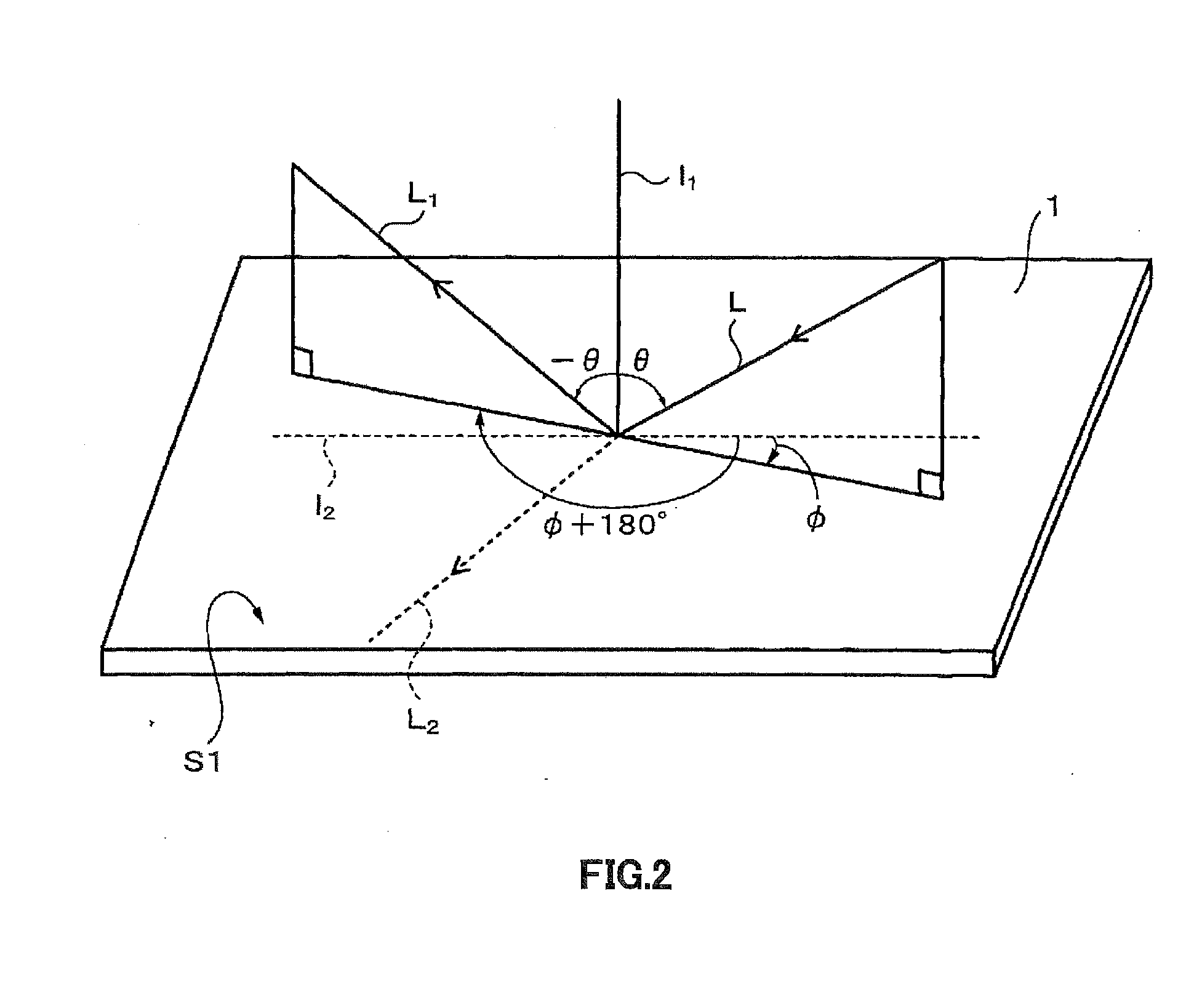
An optical element is provided with an optical layer in which a concavo-convex surface is formed on the surface thereof, and a wavelength-selective reflection layer formed on the concavo-convex surface. The wavelength-selective reflection layer directionally reflects light having a specific wavelength band selectively, while transmitting light having wavelength bands other than the specific wavelength band. The concavo-convex surface is provided with a plurality of first structural elements that are extended in a first direction within the surface of the optical layer and a plurality of second structural elements that are extended in a second direction within the surface of the optical layer, and placed to be spaced apart from each other, with the first direction and the second direction intersecting with each other.
Description
FIELD OF THE INVENTION[0001]The present technique relates to an optical element, a window material, a fitting, a solar shading device and a building. More specifically, it concerns an optical element that directionally reflects incident light.BACKGROUND OF THE INVENTION[0002]From the viewpoint of reducing an air conditioning load, a window-use film for shading solar light has been marketed. As a technique for shading solar light, a film for absorbing solar light and a film for reflecting solar light have been marketed; however, the former film becomes hot after absorbing solar light to cause a problem of a heated peripheral portion of a window that is referred to as a perimeter zone. With respect to the latter film, many techniques have been disclosed in which an optical multilayer film, a metal containing film, a transparent conductive film, or the like has been used as the reflection layer (for example, see Patent Document 1).[0003]However, since the reflection layers are formed o...
Claims
Login to View More Application Information
Patent Timeline
 Patent Type & AuthorityApplications(United States)
IPC IPC(8): G02B5/26
CPCG02B5/26E06B9/24E06B9/386E06B9/42E06B2009/2417G02B5/045G02B5/10
InventorNAGAHAMA, TSUTOMUSHIBUYA, ATSUSHI
OwnerDEXERIALS CORP