Device for transferring pre-formed layers of objects to the top of a pallet

a technology for transferring objects and objects, applied in the field of palletizing systems, can solve the problems of slow stacking rate of stacking units, inability of the upper slide to load inability of the lower slide to lift a pre-formed layer of objects, so as to reduce the cycle time of palletizing

Active Publication Date: 2014-10-02
GEBO PACKAGING SOLUTIONS ITAL
View PDF5 Cites 29 Cited by
  • Summary
  • Abstract
  • Description
  • Claims
  • Application Information

AI Technical Summary

Benefits of technology

[0031]Advantageously, the depositing head is open above the reference surface and / or at a side of the reference surface relative to the insertion direction. This provides access to the layer to be deposited when it is no longer moving. This allows, for example, placing a slip sheet on the layer to be deposited without having to secure it. This can advantageously be used when the objects forming the layer to be palletized are packs of containers enclosed in shrink-wrapped film.
[0032]Advantageously, the receiving tray is equipped with an end roller having a diameter of less than 40 mm, which is arranged so that it can be adjacent to the conveyor of the depositing head, without an intermediate connecting plate. This reduces the cycle time of the palletizer. It is then no longer necessary for the cycle to include a step of introducing an intermediate plate to ensure continuous support between the receiving tray and the conveyor of the depositing head.

Problems solved by technology

On the one hand, the lower slide is incapable of lifting a pre-formed layer of objects because the objects would fall between the bars.
On the other hand, the head of the upper slide is incapable of loading a pre-formed layer of objects because they would fall during the transfer.
Such a stacking unit has a very slow stacking rate because there are as many capture and transfer cycles as there are objects in the layer of objects to be palletized.
These multiple back-and-forth movements of the stacking unit are not only time-consuming but are also very energy inefficient, because all elements of the stacking unit must be in motion for each transferred object.
Such a palletizer has the disadvantage that the rotation of the tools and columns occupies space at the sides of the conveyor providing the pre-formed layers.
In addition, doubling the equipment is costly.
The disadvantage is that the pre-formed layer must be lifted, which increases the maintenance cost of the layer pre-forming equipment.
A disadvantage of such a palletizer is that the gantry interferes with access to the sides of said elements.

Method used


Image

  • Device for transferring pre-formed layers of objects to the top of a pallet
  • Device for transferring pre-formed layers of objects to the top of a pallet
  • Device for transferring pre-formed layers of objects to the top of a pallet

Examples


Embodiment Construction

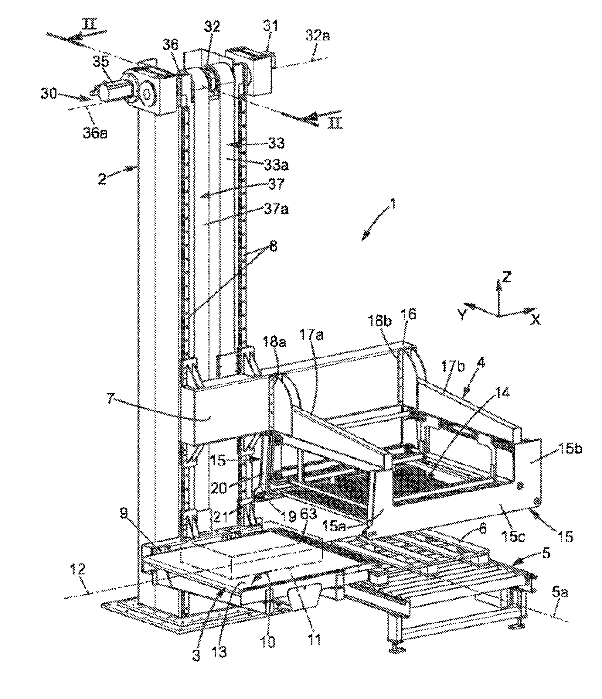
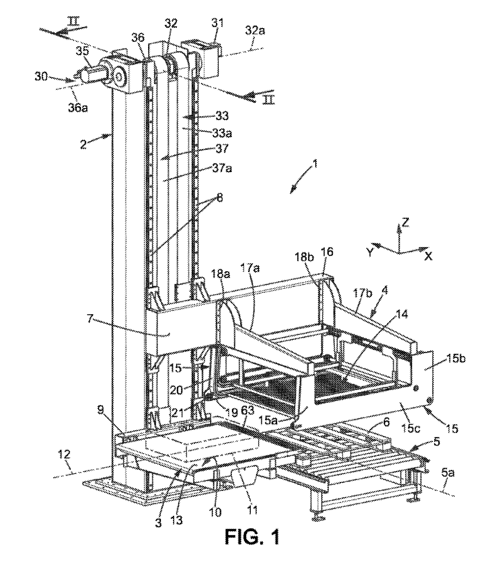
[0053]As illustrated in FIG. 1, the layer transfer device, also called a palletizer 1, comprises a guide column 2, a receiving tray 3, a depositing head 4, and a pallet conveyor 5, here conveying a pallet 6 in a horizontal and transverse direction “y”. The depositing head 4 is mechanically connected to a first carriage 7 mounted to slide translationally along a translational guide means such as, for example, a pair of rails 8. The rails 8 are parallel and run along the column 2 in a vertical direction “z”.

[0054]The receiving tray 3 is mechanically connected to a second carriage 9 mounted to slide translationally along the same pair of rails 8. The receiving tray 3 comprises a conveyor 10 for conveying layers 11 of objects. In the example, the conveyor 10 consists of a rotating endless belt extending along a horizontal conveying plane 13 and driven by a motor in a conveying direction 12 for the pre-formed layers 11. The conveying direction 12 is parallel to a horizontal and longitudi...


PUM


Abstract

Device for transferring pre-formed layers of objects to the top of a pallet. Device (1) for transferring pre-formed layers (11) of objects to the top of a pallet (6), comprising:—a guide column (2),—a depositing head (4) designed to deposit said layers (11) on top of one another on the pallet (6), and—a receiving tray (3) for receiving a pre-formed layer of objects, said receiving tray (3) being movable relative to the depositing head (4). The depositing head (4) and the receiving tray (3) are each slidably mounted in cantilever fashion only on said guide column (2).

Description

FIELD OF THE INVENTION [0001]The invention relates to palletizing systems.[0002]The invention relates in particular to devices for transferring pre-formed layers of objects to the top of a pallet. Such devices, often called “palletizers,” successively load layers of objects into a stack of layers atop a pallet, each object layer being previously shaped so as to be stackable.[0003]The invention relates to devices having a reduced cycle time for such loading.[0004]The term “preformed layers of objects to be transferred to the top of a standard pallet” is understood to mean a set of multiple objects arranged side by side, with adjacent objects being substantially in contact with and independent of each other. The largest dimension of the layer of objects is equal, or less than and substantially equal, to a standard dimension of the pallet. The main standards for pallets are 800×1200 mm in Europe and 1000×1200 in the U.S.STATE OF THE ART [0005]In 1983, document JP 58139926 described a s...

Claims


Application Information

Patent Timeline
Patent Type & Authority Applications(United States)
IPC IPC(8): B65G57/02
CPCB65G57/02B65G57/24B65G61/00
Inventor PETROVIC, ZMAJ
Owner GEBO PACKAGING SOLUTIONS ITAL
Why Eureka
Try Eureka