Rotary machine, blade wheel used in rotary machine, and blade wheel manufacturing method

a technology of blade wheel and rotary machine, which is applied in the direction of blade accessories, machines/engines, waterborne vessels, etc., can solve the problems of taking etc., and reducing the effort and time in the manufacturing process. , the effect of preventing the blade from slipping and the blade of the blade wheel

Active Publication Date: 2014-10-02
KOBE STEEL LTD
View PDF1 Cites 6 Cited by
  • Summary
  • Abstract
  • Description
  • Claims
  • Application Information

AI Technical Summary

Benefits of technology

[0022]In the blade wheel manufacturing method, since the blade of the blade wheel is shaved so that a part of the resin layer formed on the outer peripheral surface of the base material forms the shroud portion, the resin layer of the shroud portion may be easily formed compared to the c

Problems solved by technology

However, since there is a need to handle a large casing for the resin coating, it takes an effort and a time in the manufacturing process.
However, in thi

Method used


Image

  • Rotary machine, blade wheel used in rotary machine, and blade wheel manufacturing method
  • Rotary machine, blade wheel used in rotary machine, and blade wheel manufacturing method
  • Rotary machine, blade wheel used in rotary machine, and blade wheel manufacturing method

Examples


Embodiment Construction

[0030]Hereinafter, an embodiment of the present invention will be described with reference to the drawings.

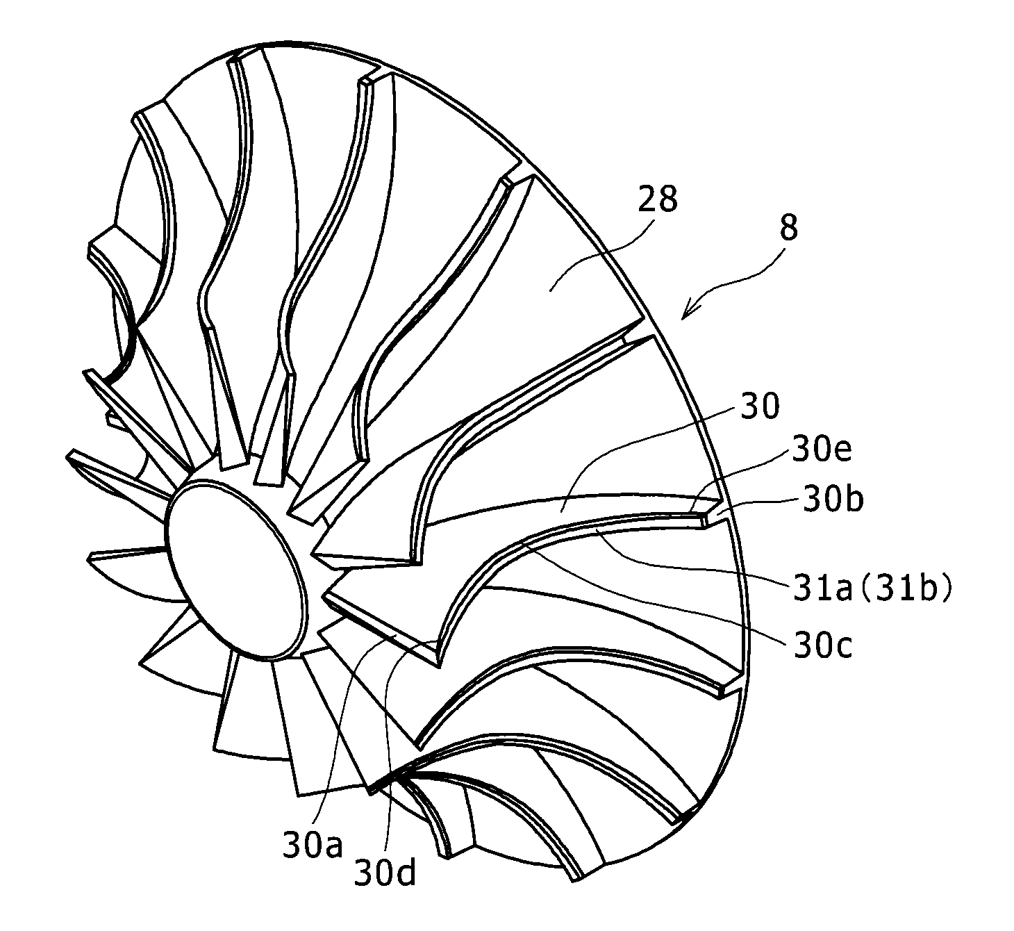
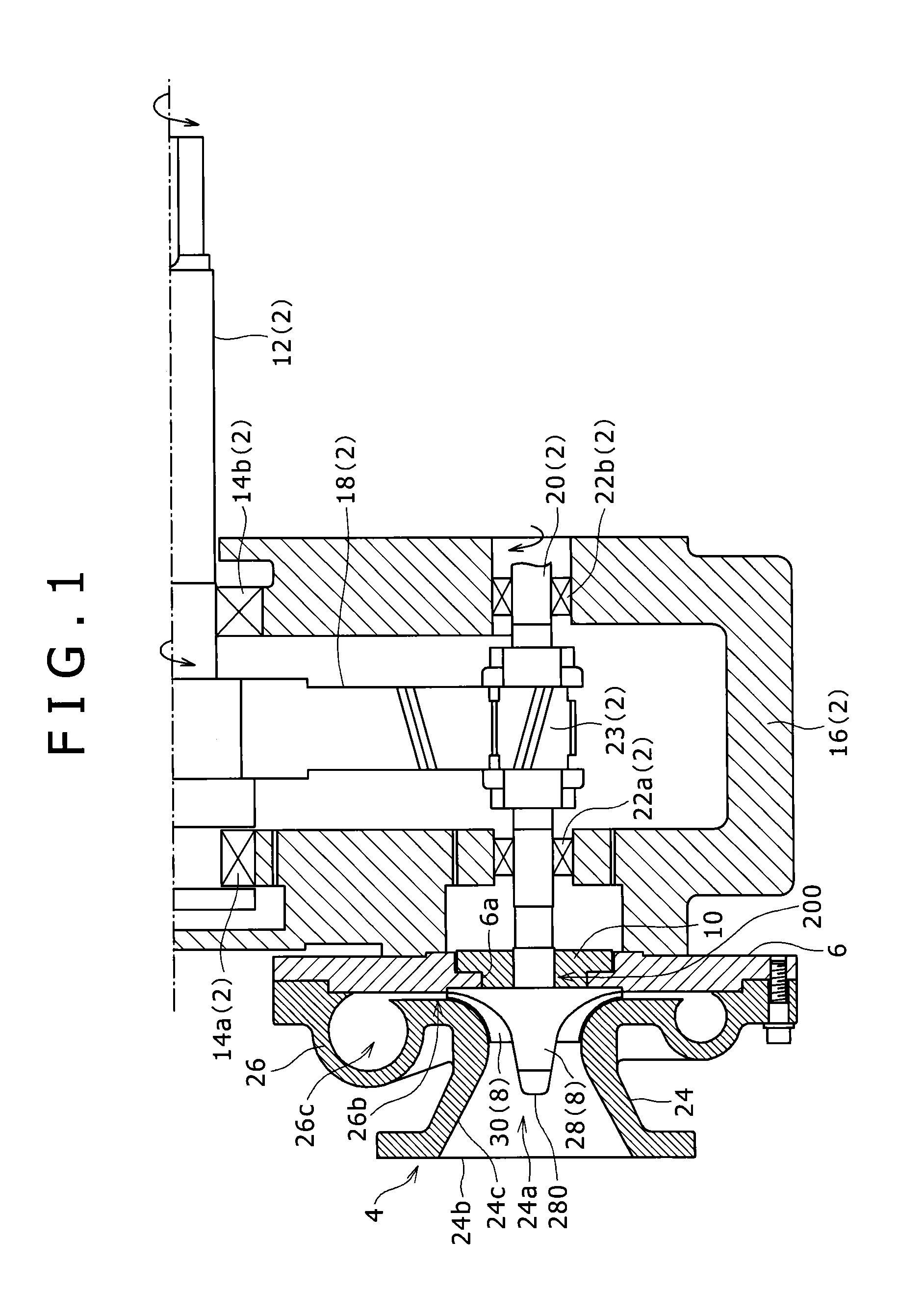
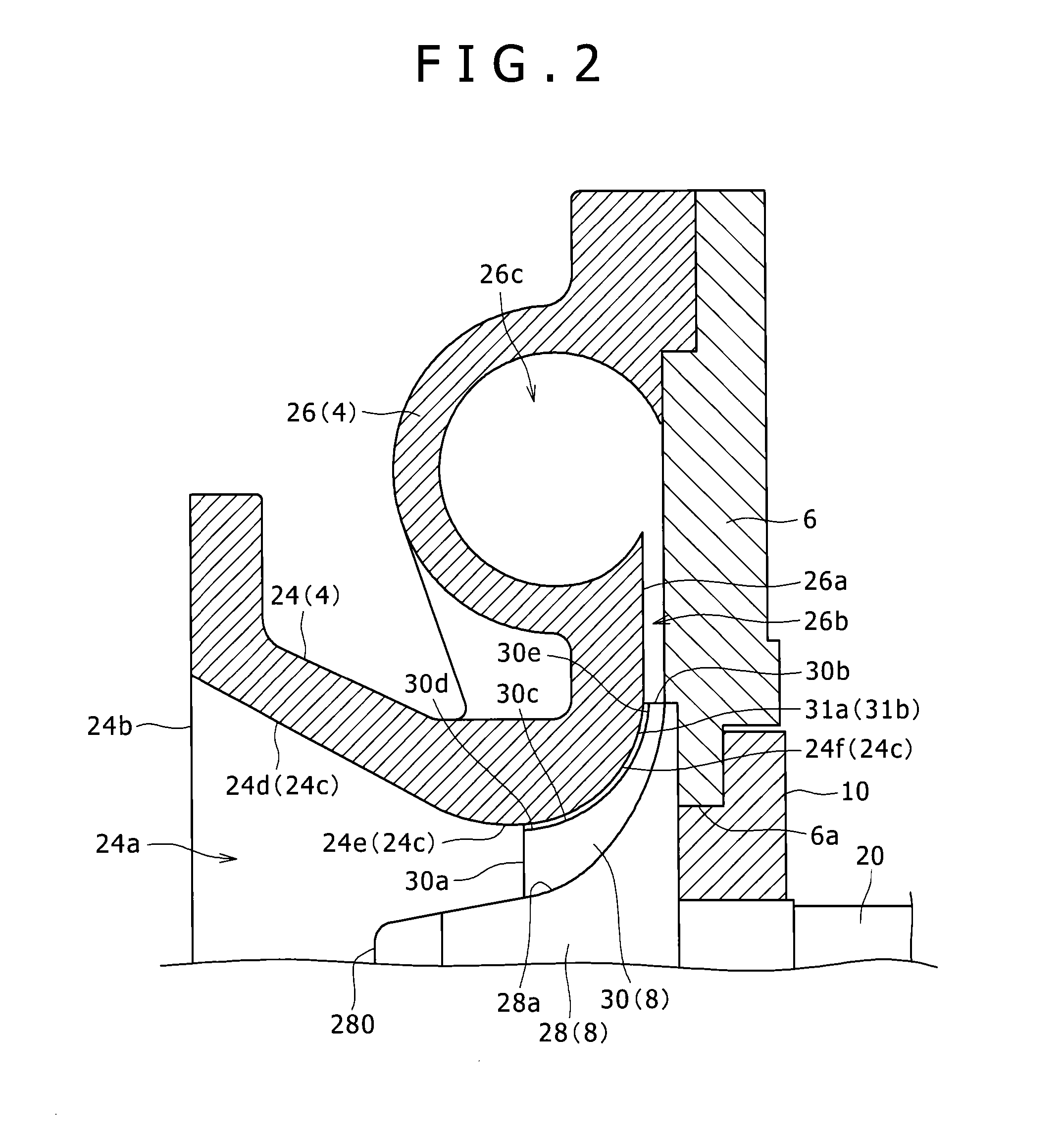
[0031]FIG. 1 is a partially cross-sectional view illustrating a compressor according to this embodiment. The compressor according to this embodiment is an example of the rotary machine of the present invention, and includes a drive mechanism 2, a compressor casing 4, a casing cover 6, an impeller 8, and a seal member 10.

[0032]The drive mechanism 2 is used to rotate the impeller 8, and includes a low-speed shaft 12, bearings 14a and 14b, a motor (not illustrated), a gear casing 16, a low-speed gear 18, a high-speed shaft 20, bearings 22a and 22b, and a high-speed gear 23.

[0033]The low-speed shaft 12 is rotatably supported by the gear casing 16 through the bearings 14a and 14b. A drive shaft of the motor (not illustrated) is connected to one end of the low-speed shaft 12.

[0034]The low-speed gear 18 is fitted to the outside of the low-speed shaft 12 at the position between the bea...


PUM


Abstract

A compressor of the present invention includes an impeller that is rotatably provided inside an accommodation portion of a compressor casing, the impeller includes a blade that extends toward an inner peripheral surface of the accommodation portion, and an outer edge of the blade facing the inner peripheral surface of the accommodation portion is provided with a shroud portion that is formed from a resin layer. With such a configuration, the wear damage of the casing and the blade of the blade wheel may be prevented, and the effort and the time in the manufacturing process may be reduced.

Description

BACKGROUND OF THE INVENTION[0001]1. Field of the Invention[0002]The present invention relates to a rotary machine, a blade wheel used in a rotary machine, and a blade wheel manufacturing method.[0003]2. Description of the Related Art[0004]Hitherto, a rotary machine with a rotatable blade wheel is known, and JP 2001-317492 A discloses a centrifugal compressor as an example of the rotary machine. The centrifugal compressor includes a casing and an impeller that corresponds to a blade wheel rotatably provided inside the casing.[0005]The casing includes a tapered inner peripheral surface that increases in diameter as it goes from one end of the impeller in the axial direction toward the other end thereof. The impeller includes a plurality of blades that extend toward the inner peripheral surface of the casing, and each blade includes an outer edge that faces the inner peripheral surface of the casing.[0006]In the inner peripheral surface of the casing, a portion on the upstream side (ai...

Claims


Application Information

Patent Timeline
IPC IPC(8): F04D29/18F04D29/60
CPCF04D29/60F04D29/18F04D25/02F04D29/023F04D29/162F04D29/284F05D2300/44F05D2300/611Y10T29/49325
Inventor FUJIOKA, KOUMEI
Owner KOBE STEEL LTD
Why Eureka
Try Eureka