
Test system

a test system and system technology, applied in the field of test systems, can solve the problems of unstable test operation, inability to accurately simulate the state of the actual machine, and inability to follow the variation well, so as to improve the followability of data

Inactive Publication Date: 2014-10-02
JTEKT CORP
View PDF19 Cites 22 Cited by
  • Summary
  • Abstract
  • Description
  • Claims
  • Application Information

AI Technical Summary

Benefits of technology

The present invention provides a test system that can accurately simulate the state of an actual machine even when there is a delay in communication between the driving simulator and the vehicle test apparatus. The invention also includes a motion control method for driving simulators and a vehicle test system that improves the real-machine reproduction accuracy of simulation. Additionally, the invention allows for quicker handling of abnormal data situations and improves the followability of control target values with respect to measured data. Overall, the invention enhances the efficiency and accuracy of testing and improves the overall test process.

Problems solved by technology

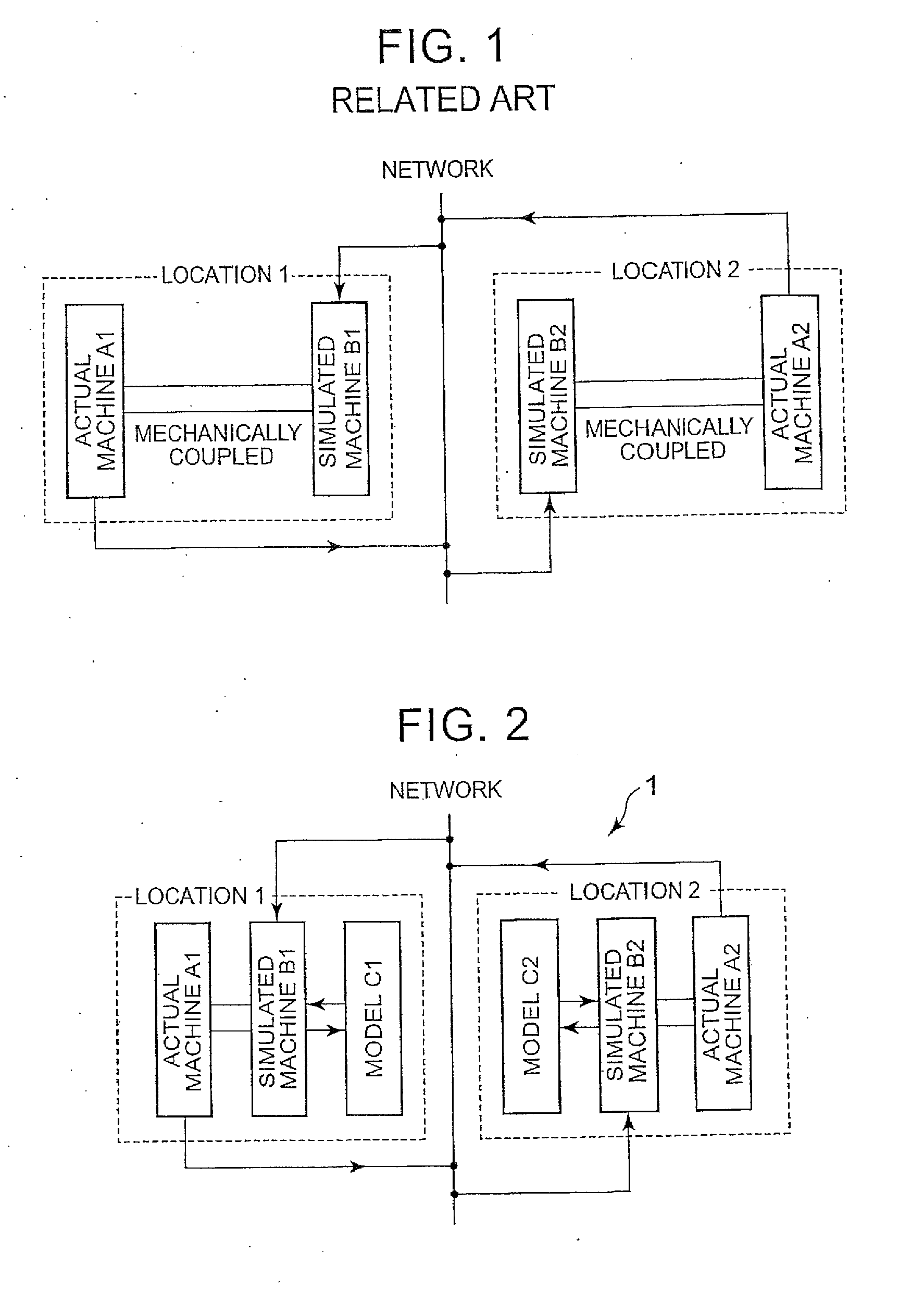
However, when a simulated machine operates on the basis of data acquired via a network and a communication cycle (which is determined depending on a transmission cycle of a packet) is long, the time corresponding to the communication cycle may be required until an actual machine transmits the next data after transmitting data, the simulated machine cannot update the data during the time, and thus the simulated machine may not correctly simulate the state of the actual machine.
Particularly, when a data value to be transmitted by communications rapidly varies, reproduction of the state may not follow the variation well and the test operation may be unstable.
In this way, a communication delay has an adverse influence on the entire test system using a network.
However, when the driving simulator and the vehicle test apparatus are simultaneously operated on the basis of the data acquired via the communication line and a communication cycle (which is determined by a process time of each terminal, a transmission cycle for a packet, and the like) is long, a delay corresponding to the communication cycle occurs until the driving simulator transmits operation data, the vehicle test apparatus calculates and transmits output data corresponding to the operation data, and the driving simulator receives the output data and feeds back the output data to a driver.
Accordingly, the driving simulator cannot update data during the delay and thus the driving simulator may not correctly determine performance of the test piece.
Particularly, when the value of the transmitted data rapidly varies, reproduction of the state may not follow the variation appropriately and the test operation may be unstable, thereby causing resonance.
Thus, when a communication delay of a predetermined time or more is present, it is difficult to perform real-time simulation and the entire vehicle test system is adversely affected.

Method used


Image

  • Test system
  • Test system
  • Test system

Examples


Embodiment Construction

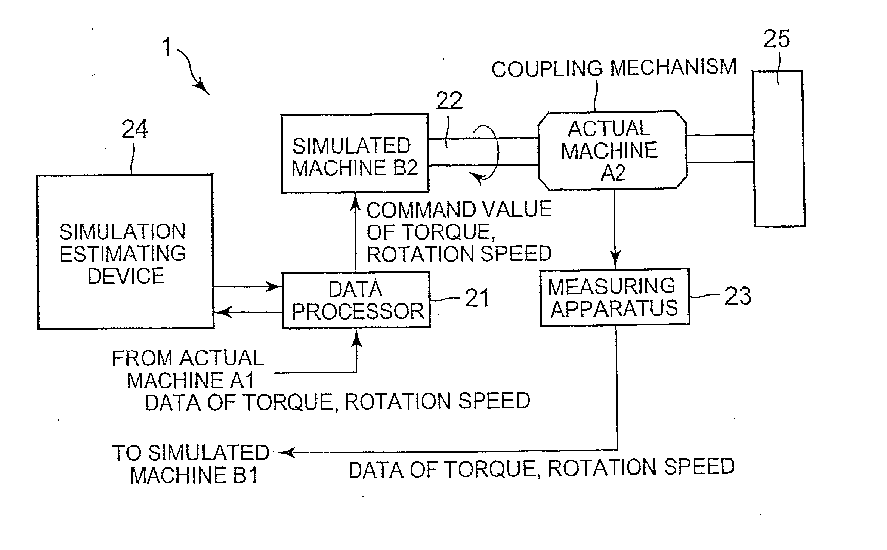
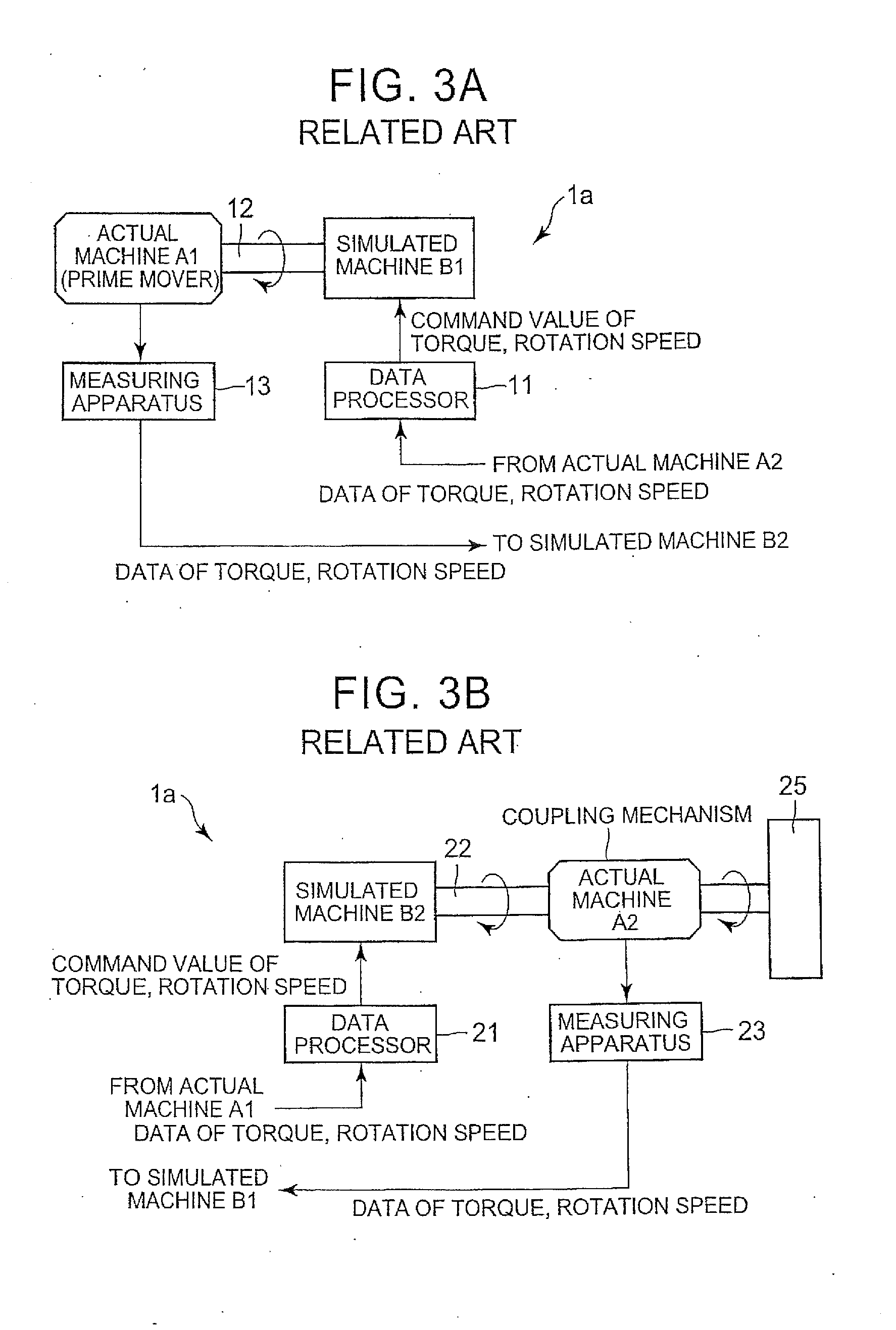
[0045]Hereinafter, a first embodiment of the invention will be described with reference to the accompanying drawings. FIG. 2 is a diagram schematically illustrating a test system 1 according to the invention in which an actual machine A1 and a simulated machine B1 are installed in location 1, a simulated machine B2 and an actual machine A2 are installed in another place (location 2), the actual machine A2 and the simulated machine B2 are mechanically coupled to each other, and the simulated machine B1 and the actual machine A1 are mechanically coupled to each other. In the embodiment of the invention, for example, it is assumed that the actual machine A2 is an electronic-control coupling mechanism which can continuously vary a ratio between driving forces of front and rear wheels from front wheels 100: rear wheels 0 in a front wheel drive to front wheels 50: rear wheels 50 by electronic control in a front wheel drive-based 4WD vehicle, and the actual machine A1 is a prime mover coup...


PUM


Abstract

A test system includes an actual machine including a test piece that is a mechanical element of a vehicle, the actual machine being installed in a first location; a control device that is installed in the first location, and controls the actual machine; a model installed in a second location away from the first location; and a data processor that is installed in the second location, and is connected to the actual machine or the control device via a communication line so that data communication is performed, the data processor acquiring data from the actual machine via the communication line so that an operation test is performed. The data processor calculates a target value for controlling the actual machine based on an output acquired by inputting the acquired data to the model, and the control device controls the actual machine based on the target value.

Description

INCORPORATION BY REFERENCE[0001]The disclosure of Japanese Patent Applications No. 2013-069254 and 2013-094407 filed on Mar. 28, 2013 and Apr. 26, 2013 including the specification, drawings, and abstract is incorporated herein by reference in its entirety.BACKGROUND OF THE INVENTION[0002]1. Field of the Invention[0003]The present invention relates to a test system using a network. The present invention also relates to a motion control method for a driving simulator and a vehicle test system.[0004]2. Description of Related Art[0005]With recent advancement of communication networks such as the Internet and intranets, techniques capable of coupling various robots to each other or coupling a robot to an interface via a network have attracted attention (for example, see Japanese Patent Application Publication No. 2006-000977 (JP 2006-000977 A)). An integration test may be carried out with mechanical elements (such as an engine, a transmission, and a steering system, which are hereinafter...

Claims


Application Information

Patent Timeline
IPC IPC(8): G01M17/007
CPCG01M17/007G01M17/00B60R16/0315G07C5/008
Inventor YOSHIMOTO, HIROSHIKADA, TOMOYASUHAYAMA, RYOUHEITAGAMI, MASAHARUMAROONIAN, ARIS
Owner JTEKT CORP
Learn More