Disk array device

a technology of array devices and disks, applied in the direction of memory address/allocation/relocation, instruments, computing, etc., can solve the problems of reducing the execution time, security problems, and taking time for processing

Inactive Publication Date: 2014-10-02
NEC CORP
View PDF3 Cites 48 Cited by
  • Summary
  • Abstract
  • Description
  • Claims
  • Application Information

AI Technical Summary

Benefits of technology

[0023]With the configuration described above, the present invention is able to

Problems solved by technology

Although a possibility of information leakage can be reduced by these techniques, as it takes a long time to execute data erasure due to an increase in the storage capacity in recent years, reduction of the execution time is required.
In the case of complete erasure in units of physical disks

Method used


Image

  • Disk array device
  • Disk array device
  • Disk array device

Examples


first exemplary embodiment

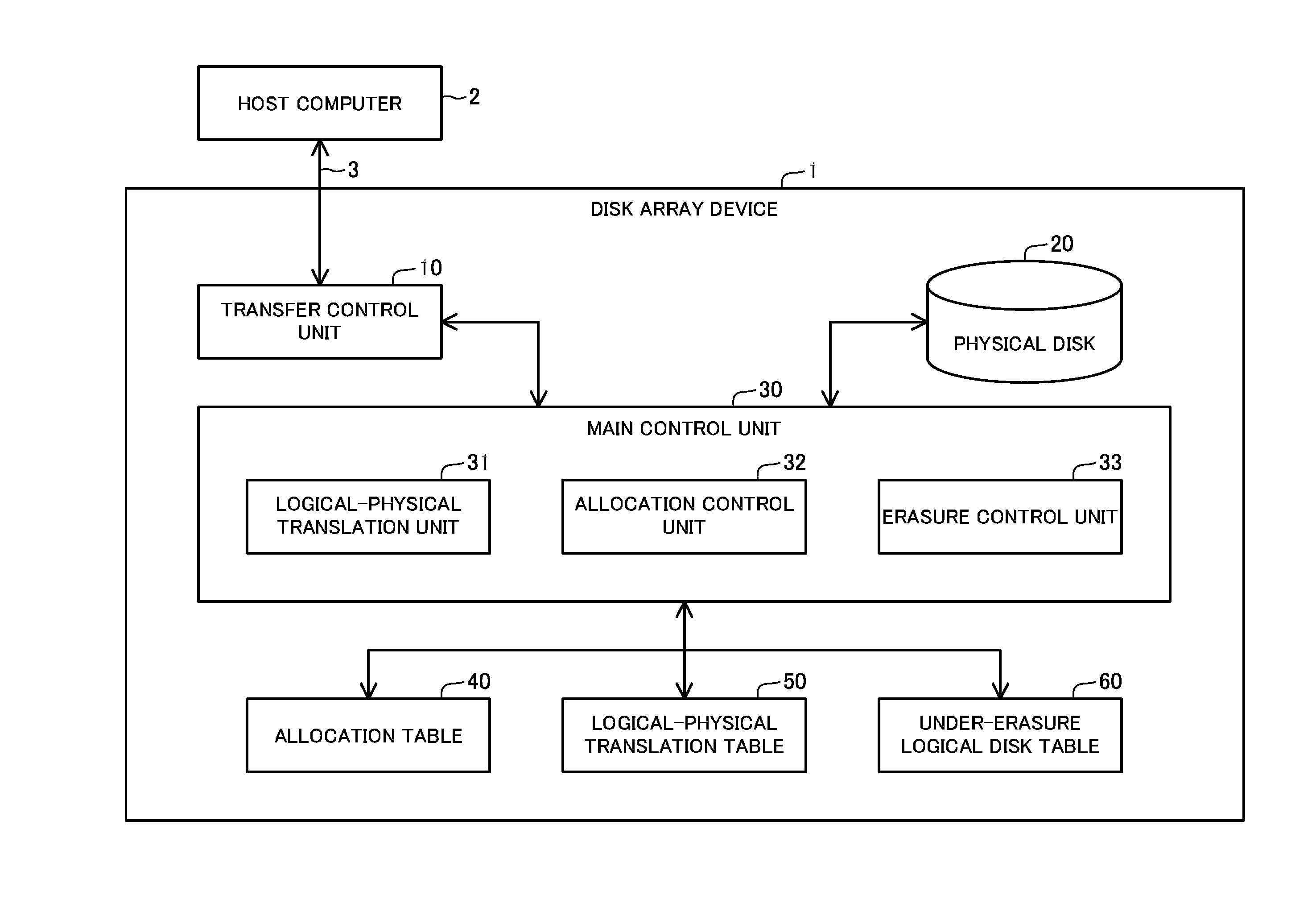
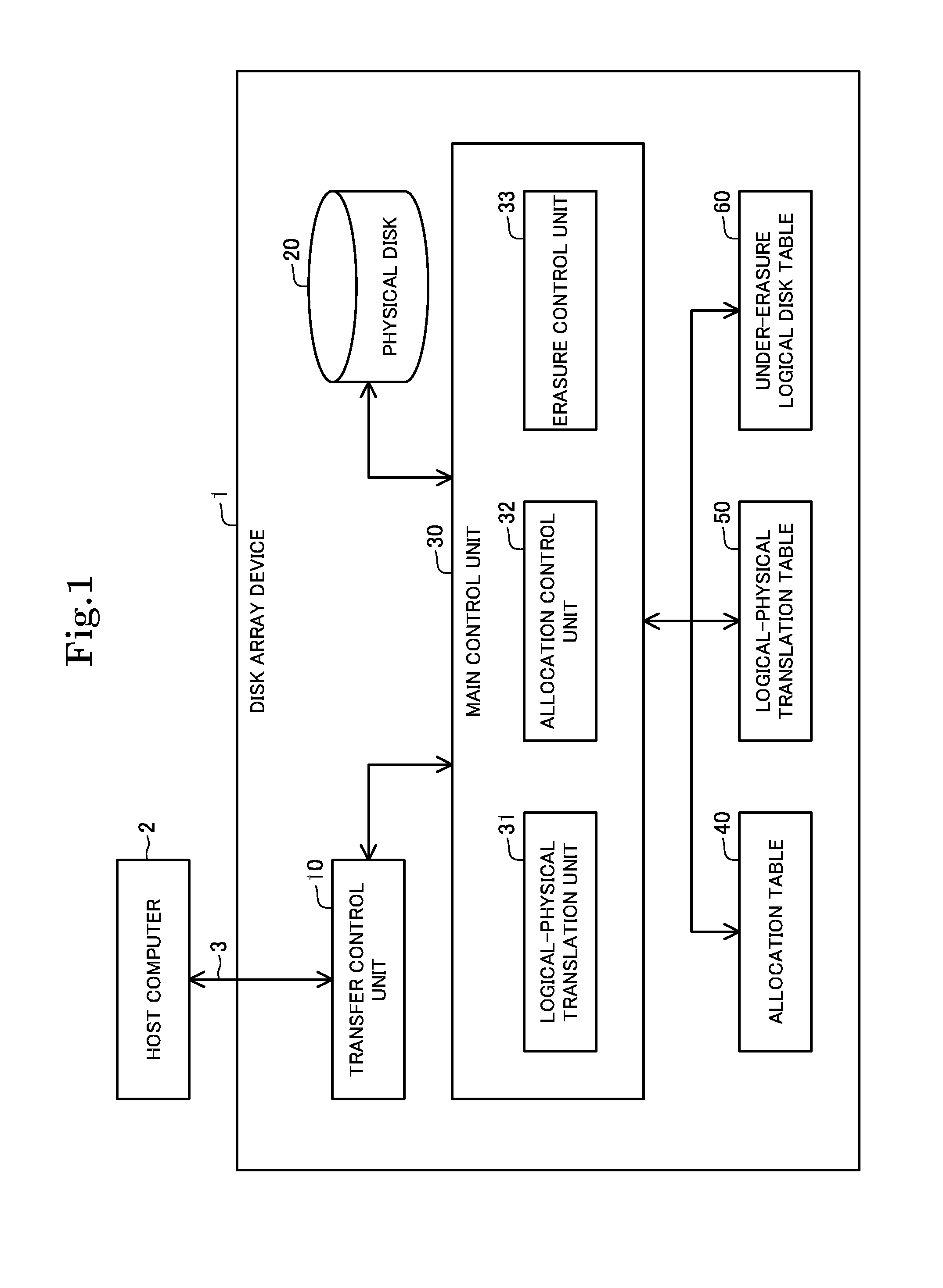
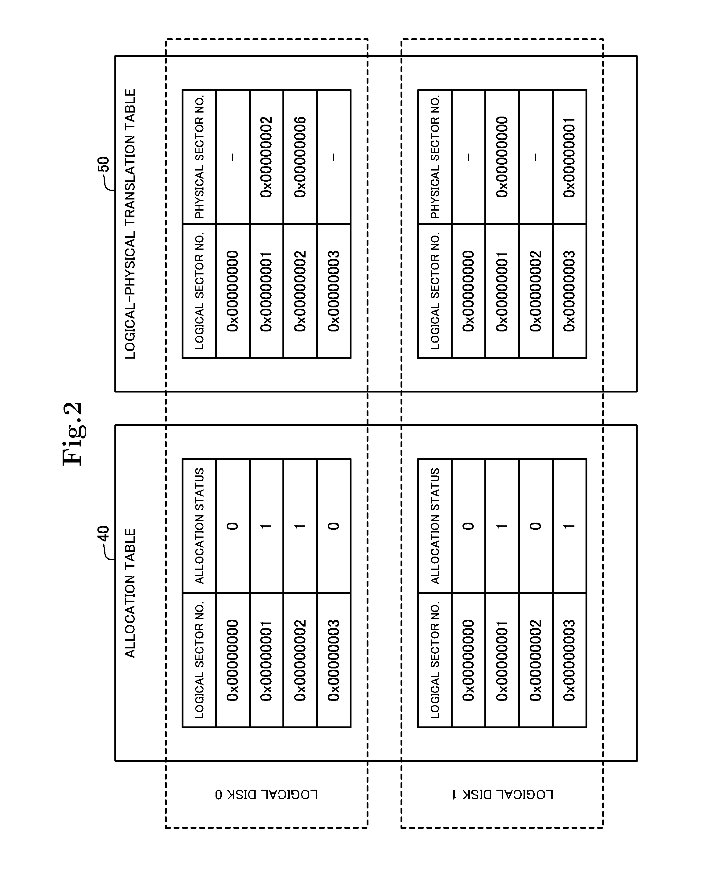
[0034]A first exemplary embodiment of the present invention will be described with reference to FIGS. 1 to 8. FIG. 1 is a block diagram showing a configuration of a disk array device. FIGS. 2 and 3 show exemplary data stored in the disk array device. FIGS. 4A to 7 are flowcharts showing the operation of the disk array device. FIG. 8 is a block diagram showing another exemplary configuration of a disk array device.

[Configuration]

[0035]As shown in FIG. 1, a disk array device 1 according to the present embodiment is connected with a host computer 2 via an interface 3. The disk array device 1 includes a transfer control unit 10, a physical disk 20, and a main control unit 30. The interface 3 is connected with the transfer control unit 10, the transfer control unit 10 is connected with the main control unit 30, and the main control unit 30 is connected with the physical disk 20. It should be noted that the transfer control unit 10 and the main control unit 30 are implemented by a program...


PUM


Abstract

The disk array device includes an allocation control unit that allocates a physical sector to a logical sector, and an erasure control unit that erases data written on a logical sector. The allocation control unit stores a logical sector and a physical sector allocated thereto in a translation table in association with each other, and stores allocation information representing that the physical sector is allocated to the logical sector, in an allocation table. The erasure control unit registers logical disk information specifying a logical disk, to which an erasure request has been made, in an under-erasure table, specifies a physical sector allocated to a logical sector formed in the logical disk to which the erasure request has been made, based on the allocation table and the translation table, and performs erasure processing on the specified physical sector.

Description

INCORPORATION BY REFERENCE[0001]The present application is based upon and claims the benefit of priority from Japanese patent application No. 2013-063367, filed on Mar. 26, 2013, the disclosure of which is incorporated herein in its entirety by reference.TECHNICAL FIELD[0002]The present invention relates to a disk array device, and in particular, to a disk array device in which a physical disk is allocated to a logical disk in response to a write request.BACKGROUND ART[0003]In a magnetic storage device such as a hard disk drive, even though data is erased, there is a possibility that the data is read from the residing magnetism. As such, attention is focused on techniques called complete data erasure or sanitization. In complete data erasure, predetermined data is overwritten repeatedly in a predetermined sequence to the entire area of a magnetic storage device so as to make it impossible to read data. Although a possibility of information leakage can be reduced by these techniques,...

Claims


Application Information

Patent Timeline
IPC IPC(8): G06F12/02G06F12/10
CPCG06F12/10G06F12/023G06F21/78G06F2221/2143G06F3/0604G06F3/0608G06F3/061G06F3/0652G06F3/0665G06F3/0689
Inventor NAKAGAWA, SHINTA
Owner NEC CORP
Why Eureka
Try Eureka