Wireless sensor device and system comprising the same

Inactive Publication Date: 2014-10-09
CREATOR TEKNISK UTVECKLING
View PDF0 Cites 18 Cited by
  • Summary
  • Abstract
  • Description
  • Claims
  • Application Information

AI Technical Summary

Benefits of technology

[0012]In this way, there is provided a wireless sensor device suitable for a high voltage environment such as mounting on a disconnector, which sensor device does not suffer from problems due to corona effects, or sparking because of the high voltage environment, since the sensor device has no projecting parts, and is designed to resist high electric fields and/or voltages because of a round design having no sharp edges.
[0013]As with all measuring or monitoring, a reason for temperature measuring or monitoring is to avoid failures by giving an alarm before failure develops into a fault. The alarm should be early enough to make useful precautions possible at a suitable moment. Thus, frequent, or continuous temperature monitoring is a great a

Problems solved by technology

These high currents may give rise to high temperatures in a disconnector due to increasing resistance of the disconnector, in particular if the disconnector is inferior, or worn out.
This of course is cumbersome and expensive because of too-early exchange of the mechanical parts.
A drawback with thermo photographing is that since this is a cumbersome and expensive method frequent measuring of temperature in disconnectors, or other mechanical parts cannot be achieved because of practical and economical reasons.
During exchange of disconnectors or other mechanical parts power has to be shut down, which is another drawback since availability is decreased due to the power shut down.
One failure that is possible when the disconnector temperature in a switchgear has increased is that the disconnector has

Method used


Image

  • Wireless sensor device and system comprising the same
  • Wireless sensor device and system comprising the same
  • Wireless sensor device and system comprising the same

Examples


Embodiment Construction

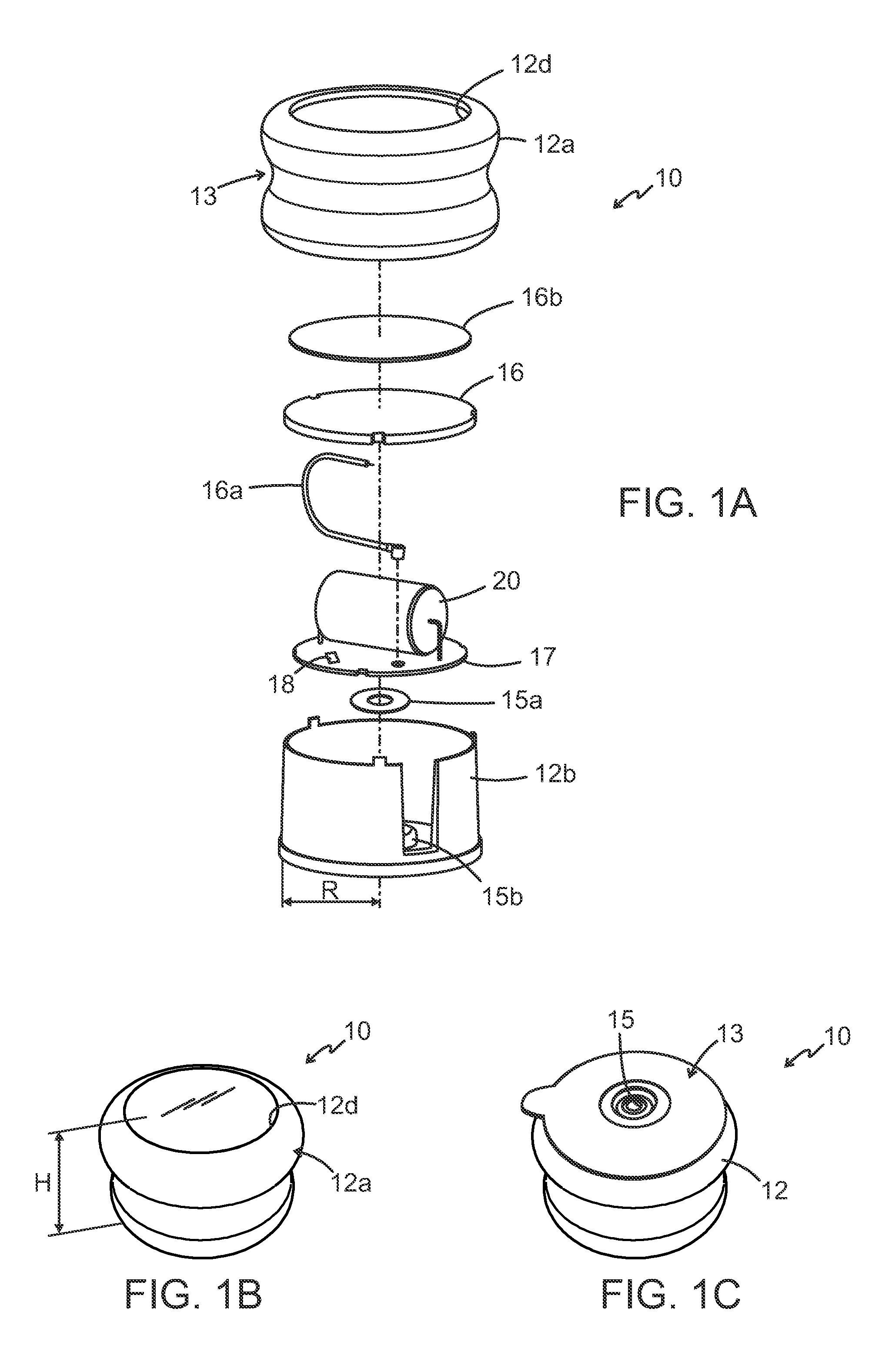
[0025]Referring now to FIG. 1a, which shows a perspective view of a disassembled sensor device according to an embodiment of the present invention, the principle of the present invention will be described as follows.

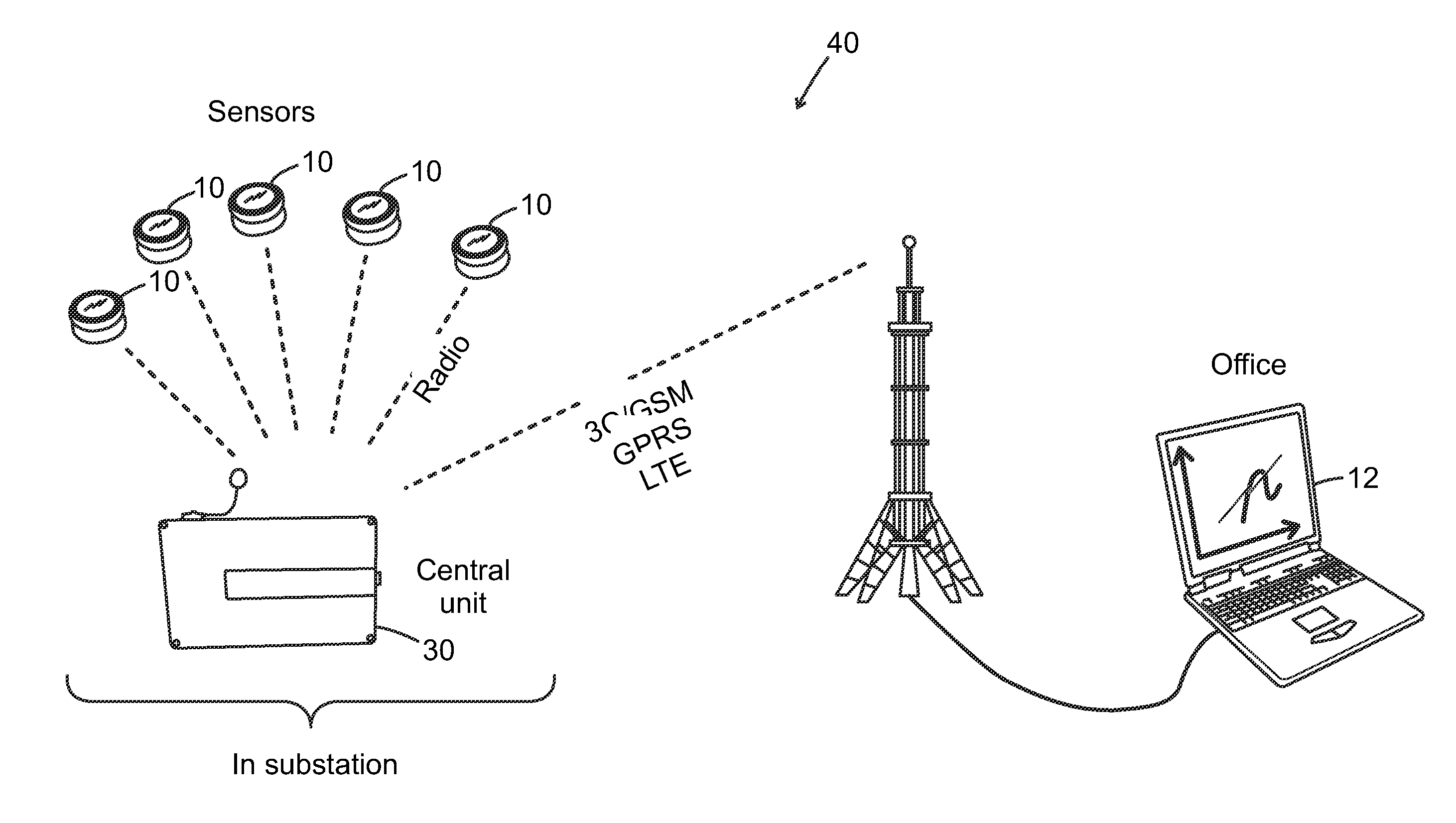
[0026]FIG. 1a shows a wireless sensor device 10 according to an embodiment of the present invention suitable for application in a high-voltage environment, or medium voltage environment, such as mounting the sensor device 10 on a disconnector (not shown in this figure) in a power sub station (not shown). The sensor device 10 comprises a housing 12 at least partly surrounding a communication unit 16, a control unit 18 for measuring and / or monitoring one or more parameter(s) such as temperature outside Toutside the housing 12 by means of temperature sensor 15 (See FIG. 1C). Typically, the temperature sensor 15 is arranged to also measure temperature inside Tinside, the housing 12. The communication unit 16 typically comprises an antenna and a combined receiver / transmitter,...


PUM


Abstract

A wireless sensor device (10) for a high-voltage environment, which device (10) comprises a housing (12), a control unit (18) for monitoring one or more variable(s) (T) and a power supply unit (20), wherein the housing (12) is designed such that an electric field (E) is minimized and the communication unit (16) is arranged partly inside the housing (12).

Description

FIELD OF THE INVENTION[0001]The present invention relates to a wireless sensor device. More specifically, the present invention relates to a wireless sensor device for a high-voltage environment such as power production, transmission and distribution, as well as to power systems for railways. The present invention is also related to a system including a plurality of such sensor devices.BACKGROUND OF THE INVENTION[0002]Today, high voltage applications such as high voltage systems with switchgear are known. In particular switchgear containing separate circuit breakers and disconnectors, or combined units with so-called “disconnecting circuit breakers” are used for instance in power sub-stations. In short, a disconnector is a mechanical power switch.[0003]By the term “high voltage” is herein meant a voltage typically ranging from 6 kV-1400 kV. Currents can be as high as say 6 000 A, but are typically not higher than 2 000-3 000 A in such high voltage applications. These high currents m...

Claims


Application Information

Patent Timeline
IPC IPC(8): G08C17/02G01K1/02G01K1/08G01K1/024
CPCG01R1/18G01R15/142H04Q9/00G08C17/02G01K1/024G01K1/026G01K3/005H04Q2209/823G01R31/327G08C17/00H05K9/0049
Inventor HUMMEL, KJELLLISSMATS, JONKJELLBERG, ANDERSPETTERSSON, ERLINGGUDMUNDSSON, MICHAELSVEDLUND, JERRY
Owner CREATOR TEKNISK UTVECKLING
Why Eureka
Try Eureka