Medical apparatus for displaying the catheter placement position

a technology of medical equipment and positioning position, which is applied in the field of brachytherapy, can solve the problems of inaccurate treatment plan and difficulty for physicians in placing catheters in exactly the correction position, and achieve the effect of inexpensively and accurately determining

Inactive Publication Date: 2014-10-09
KONINKLJIJKE PHILIPS NV
View PDF8 Cites 22 Cited by
  • Summary
  • Abstract
  • Description
  • Claims
  • Application Information

AI Technical Summary

Benefits of technology

[0033]Execution of the instructions further causes the processor to generate the ultrasonic pulse using the piezoelectric transducer of each of the multiple brachytherapy catheters. Execution of the instructions further causes the processor to receive the ultrasonic pulse with at least one other of the multiple brachytherapy catheters. Execution of the instructions further causes the processor to determine a delay for the received ultrasonic pulse. Execution of the instructions further causes the processor to store the delay in the memory as the catheter position. The delay may be translated into an estimated distance or the actual delay may be stored as the catheter position. The catheter position, the repeat catheter position and the predetermined distance may also be interpreted as a measurement which is indicative of a distance such as a delay. This embodiment may be advantageous because it provides a means of inexpensively and accurately determining if the catheters have moved. During a typical therapy session four or five or even more catheters may be placed within a subject.
[0034]In another embodiment each of the multiple brachytherapy catheters comprises a shape-sensing fiber optic. The catheter location verification system is configured for measuring the catheter position using the shape-sensing fiber optic of each of the multiple brachytherapy catheters. Execution of the instructions further causes the processor to measure the catheter position using the shape-sensing fiber optic of each of the multiple brachytherapy catheters. Note to self: insert data about shape-sensing fiber optics here. This embodiment may be advantageous because the shape-sensing fiber optics are able to determine an absolute location of the fiber optic which is embedded in the brachytherapy catheter.
[0035]In another embodiment execution of the instructions further causes the processor to segment the image reconstructed from the guidance magnetic resonance data to identify catheter locations. Execution of the instructions further causes the processor to display the catheter locations on the display.
[0036]In another embodiment the medical apparatus further comprises a catheter actuator configured for controlling the position of the multiple brachytherapy catheters as a function of time. Execution of the instructions further causes the processor to control the position of the multiple brachytherapy catheters by controlling the catheter actuator in accordance with the catheter control commands. This embodiment is beneficial because the medical apparatus is capable of automating the positioning and actuation of the radiation sources within the brachytherapy catheters.

Problems solved by technology

A disadvantage of current methods of guiding brachytherapy catheters is that it is very difficult for a physician to place the catheter in exactly the correction position.
Catheter placement and the location of radioactive sources within the catheters as a function of time can be calculated before catheter placement, but it is very likely that after the catheters have been placed that the resulting treatment plan will be incorrect.

Method used


Image

  • Medical apparatus for displaying the catheter placement position
  • Medical apparatus for displaying the catheter placement position
  • Medical apparatus for displaying the catheter placement position

Examples


Embodiment Construction

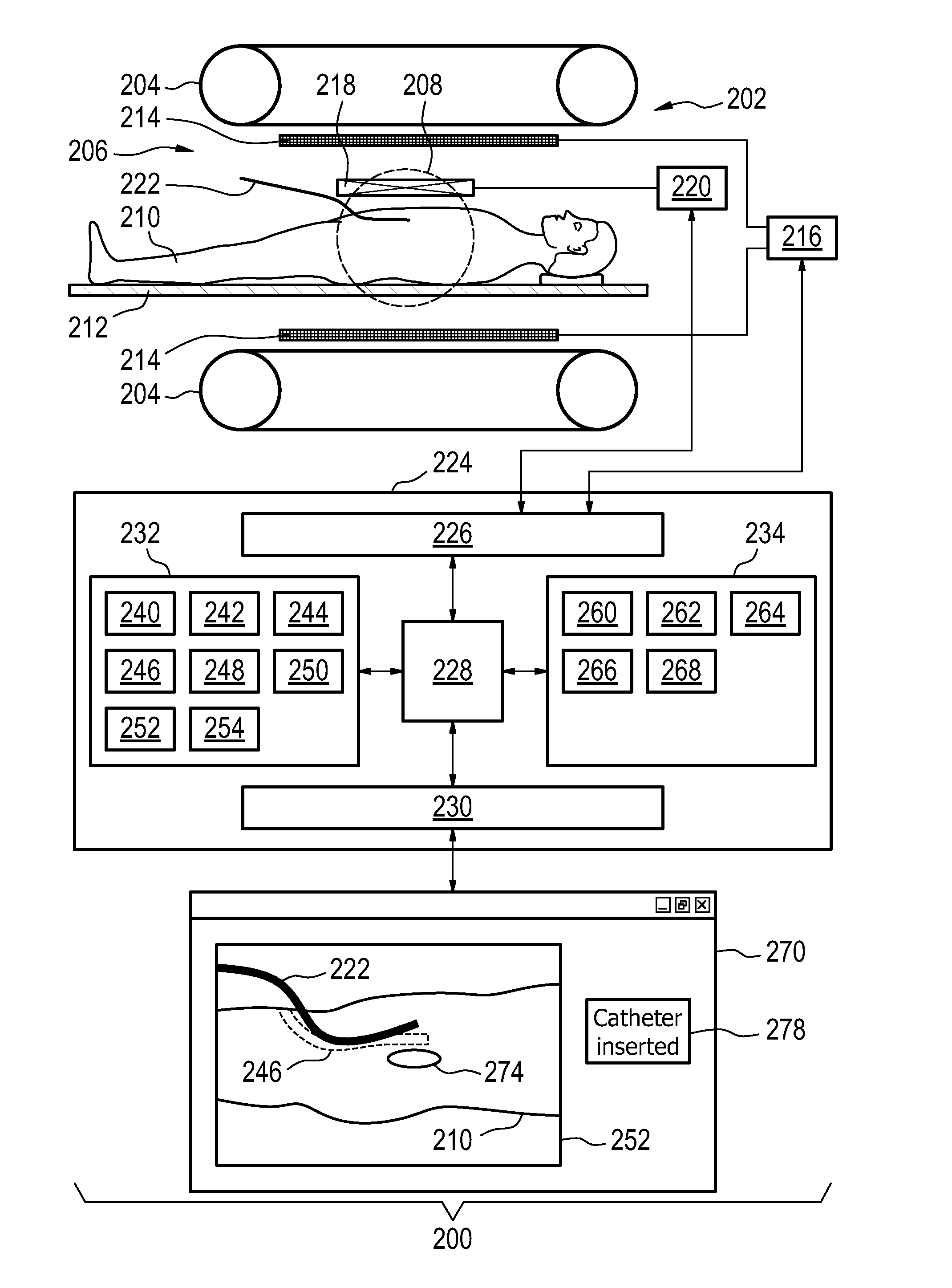
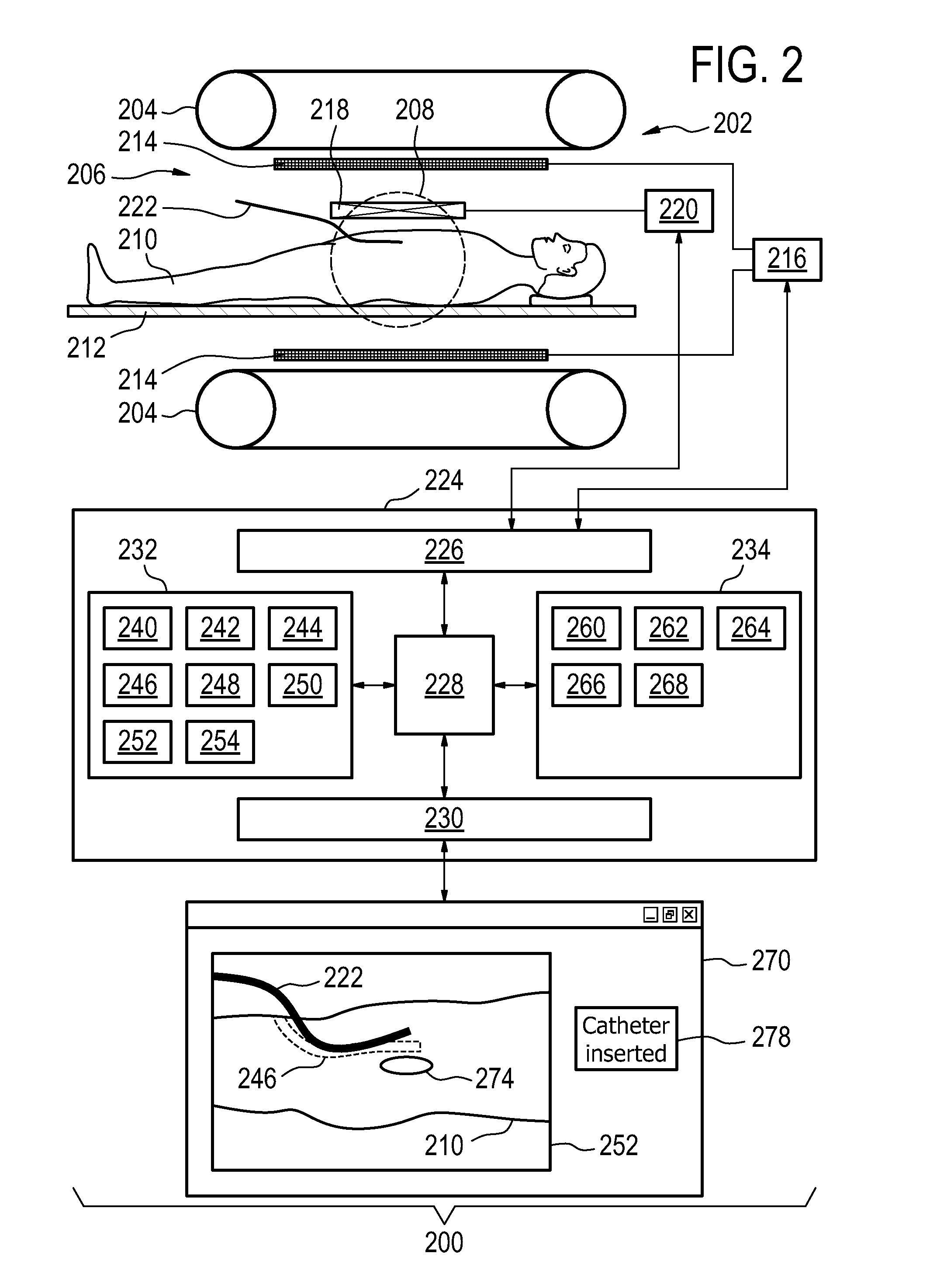
[0067]Like numbered elements in these figures are either equivalent elements or perform the same function. Elements which have been discussed previously will not necessarily be discussed in later figures if the function is equivalent.

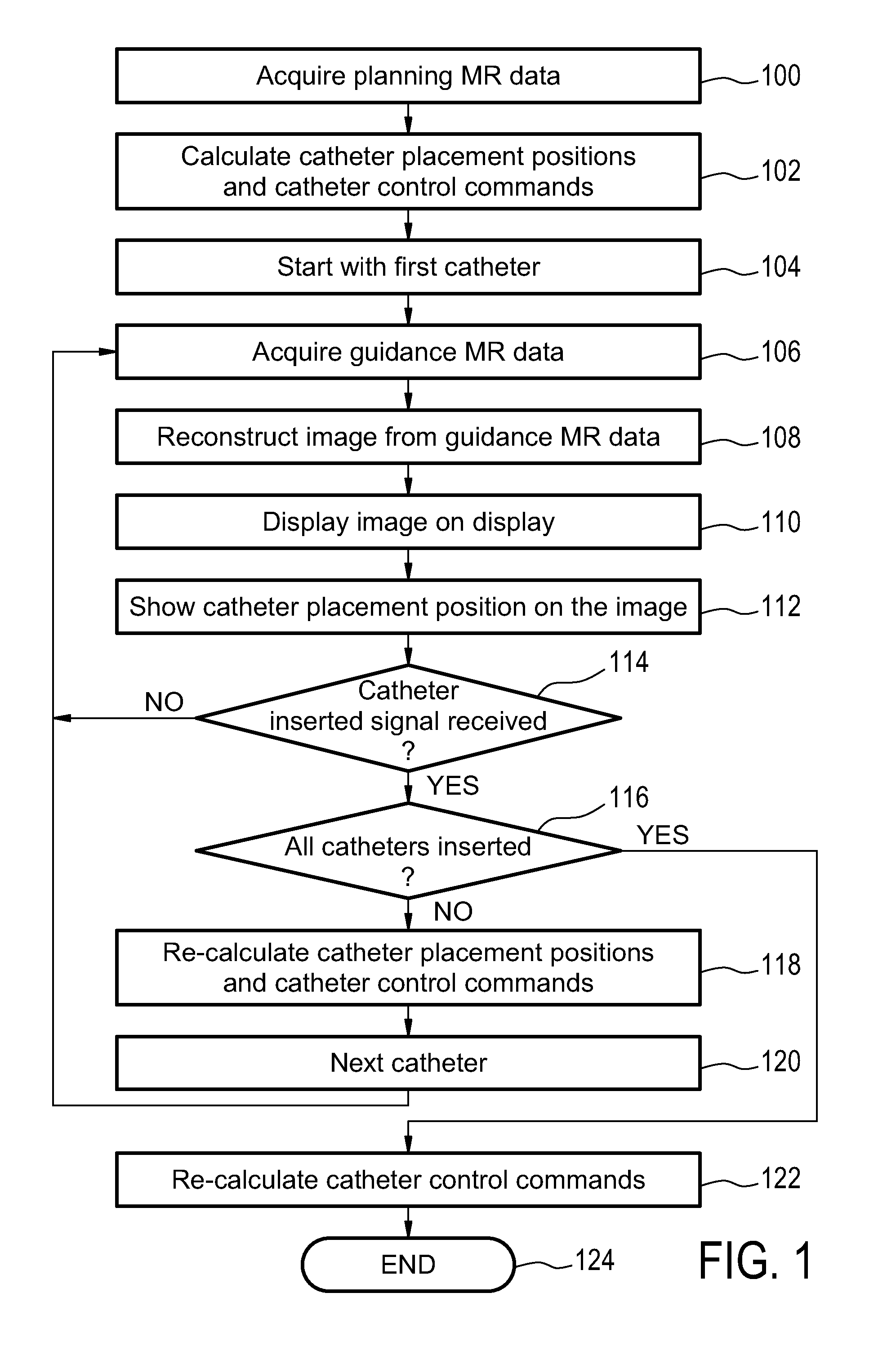
[0068]FIG. 1 shows a flow diagram which illustrates a method according to an embodiment of the invention. In step 100 planning magnetic resonance data is acquired. Next in step 102 catheter placement positions and catheter control commands are calculated using the planning magnetic resonance data and a brachytherapy treatment plan. The step of receiving a brachytherapy treatment plan is not shown. Next in step 104 the method is performed for the first catheter. In step 106 guidance magnetic resonance data is acquired. An image is reconstructed from the guidance magnetic resonance data in step 108. This image is then displayed 110 on a display. Next in step 112 the catheter placement position that was calculated in step 102 is shown on the image. After o...


PUM


Abstract

The invention provides for a medical apparatus (200, 300, 400) comprising: a magnetic resonance imaging system (202), a display (270), a processor (228), and a memory (234) for storing instructions for the processor. The instructions causes the processor to receive a brachytherapy treatment plan (240), acquire (100) planning magnetic resonance data (244), calculate (102) a catheter placement positions (246, 900, 902) and a catheter control commands (248) the brachytherapy catheters. The instructions cause the processor, for each catheter placement position, to repeatedly: acquire (106) guidance magnetic resonance data (250), reconstruct (108) an image (252, 500), display (110) the image and the catheter placement position on the display, receive (114) a catheter inserted signal from a user interface, segment (116) the image to determine the catheter placement position after receiving the catheter inserted signal, recalculate (116) the catheter placement positions for each remaining catheter placement position after receiving the catheter inserted signal, and recalculate (116) the catheter control command for all of the multiple catheters after receiving the catheter inserted signal.

Description

TECHNICAL FIELD[0001]The invention relates to brachytherapy, in particular it relates to magnetic resonance guided brachytherapy.BACKGROUND OF THE INVENTION[0002]High dose rate (HDR) brachytherapy is a very promising method for treating different kinds of tumors. One or more catheters are inserted directly into one or several tumor(s) in a minimally invasive procedure. Through these catheters, small radioactive seeds can be shifted to pre-defined positions in order to deposit a high radiation dose precisely in the lesion with only minimal damage of surrounding healthy tissue compared to other focal techniques. At the same time HDR brachytherapy allows treatment of larger tumors and is unlike Radio-Frequency Ablation (RFA) not prone to cooling effects of nearby vessels. HDR brachytherapy allows accurate focal treatment in deformable or even moving tissue.[0003]Current treatment planning software optimizes the dose distribution after the intervention, when the catheters are already pl...

Claims


Application Information

Patent Timeline
Patent Type & Authority Applications(United States)
IPC IPC(8): A61N5/10
CPCA61N5/1007A61N5/1039A61N5/1027A61N5/1064A61N2005/1024A61N2005/1055
Inventor AMTHOR, THOMAS ERIKUHLEMANN, FALKKRUEGER, SASCHAWEISS, STEFFENHOLTHUIZEN, RONALDUS FREDERIK JOHANNESWIRTZ, DANIELKOKENM, PETER
Owner KONINKLJIJKE PHILIPS NV
Why Eureka
Try Eureka