Vehicle noise-proof cover

a technology for vehicles and covers, applied in the field of noise-proof covers, can solve problems such as fuel economy reduction, and achieve the effects of increasing the heat dissipation effect, facilitating heat dissipation, and increasing the temperature differen

Active Publication Date: 2014-10-16
SUMITOMO RIKO CO LTD
View PDF12 Cites 4 Cited by
  • Summary
  • Abstract
  • Description
  • Claims
  • Application Information

AI Technical Summary

Benefits of technology

[0031]During traveling of the vehicle, the engine hood is exposed to air and cooled. Accordingly, the heat dissipation effect can further be increased by making the heat dissipation member, which is placed on the other end (cooling end) of the thermoelectric element, in contact with the engine hood. However, in order to protect pedestrians in the event of a collision, a certain amount of space (shock absorbing space) needs to be secured between the engine hood and the engine cover. Accordingly, in the case where the heat dissipation member is made of a hard material such as a metal, the heat dissipation member cannot be made in contact with the engine hood.
[0032]In this respect, according to this configuration, a base material of the heat dissipation member is urethane foam. Accordingly, the heat dissipation member is elastic and relatively soft. The heat dissipation member can therefore be made in contact with the engine hood. This facilitates heat dissipation from the other end of the thermoelectric element, and can further increase the temperature difference between the one end and the other end. Moreover, since the heat dissipation member is elastic, the heat dissipation member is compressed by a pressing force from the engine hood, whereby a gap (air layer) between the heat dissipation member and the engine hood is eliminated, and heat transfer capability to the engine hood can be improved.

Problems solved by technology

Accordingly, an increase in power supply causes reduction in fuel economy.

Method used


Image

  • Vehicle noise-proof cover
  • Vehicle noise-proof cover
  • Vehicle noise-proof cover

Examples


first embodiment

Configuration

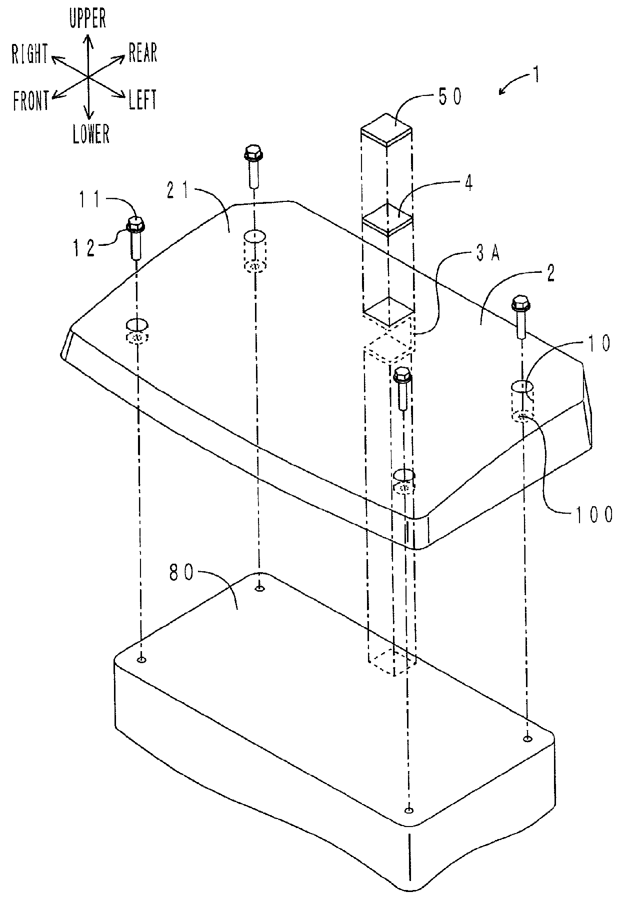
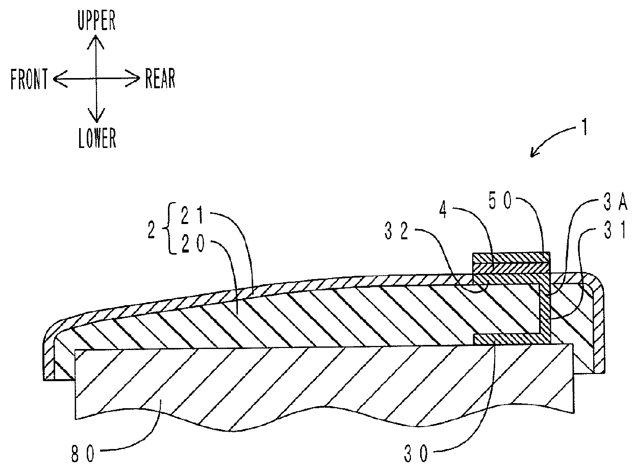
[0045]First, the configuration of an engine cover of the present embodiment will be described. FIG. 1 is an exploded perspective view of the engine cover of the present embodiment. FIG. 2 is a sectional view taken along the front-rear direction of the engine cover. In FIGS. 1 and 2, the directions are defined as viewed facing forward from the rear of the vehicle. As shown in FIGS. 1 and 2, an engine cover 1 is placed so as to cover a cylinder head cover 80 as a constituent member of an engine. A recess 10 for a bolt 11 to be inserted therein is formed in the four corners of the engine cover 1. Each of the four recesses 10 has an insertion hole 100 for the bolt 11 to be inserted therethrough. The bolt 11 extends through the insertion hole 100 via a washer 12, and is fixed to the cylinder head cover 80, whereby the engine cover 1 is attached to the upper surface of the cylinder head cover 80.

[0046]The engine cover 1 includes a cover body 2, a heat supply member 3A, a the...

second embodiment

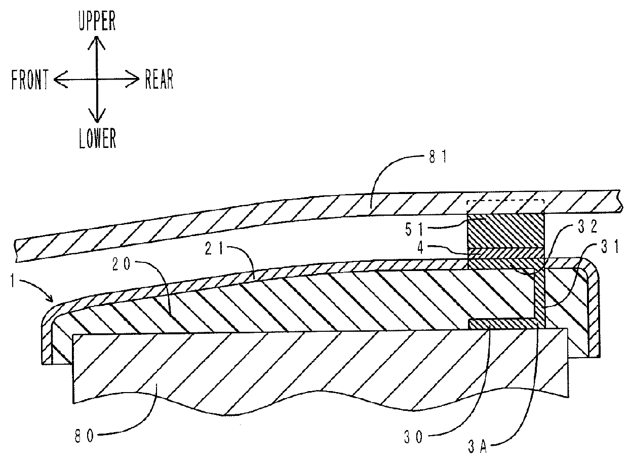
[0060]An engine cover of the present embodiment is different from that of the first embodiment in that the heat dissipation plate made of aluminum is replaced with a heat dissipation member as a urethane foam molded article and in that the heat dissipation member is in contact with an engine hood. Only the differences will be described be low.

[0061]FIG. 3 is a sectional view taken along the front-rear direction of the engine cover of the present embodiment. The portions corresponding to those of FIG. 2 are denoted by the same reference characters. As shown in FIG. 3, an engine hood 81 is placed over the engine cover 1. A heat dissipation member 51 is placed on the upper surface of the thermoelectric element 4. The heat dissipation member 51 is interposed between the engine hood 81 and the thermoelectric element 4. The heat dissipation member 51 is placed in such a state that it is compressed in the vertical direction from its natural state (shown by broken line in FIG. 3) by a press...

third embodiment

[0065]An engine cover of the present embodiment is different from the engine cover of the first embodiment in the position and shape of the heat supply member. Only the differences will be described below.

[0066]FIG. 4 is a sectional view taken along the front-rear direction of the engine cover of the present embodiment. The portions corresponding to those of FIG. 2 are denoted by the same reference characters. As shown in FIGS. 1 and 4, a heat supply member 3B is placed on the right rear part of the cover body 2. The heat supply member 313 has a stepped shape in the front-rear direction. The heat supply member 3B has the heat collection portion 30, the heat supply portion 32, and the heat transfer portion 31.

[0067]The heat collection portion 30 is made of aluminum and is in the shape of a rectangular plate. The heat collection portion 30 is placed on the lower surface side (back surface side) of the engine cover 1. The heat collection portion 30 is embedded in the noise absorption l...


PUM


Abstract

A vehicle noise-proof cover is provided which includes a thermoelectric element and which is capable of efficiently generating electric power. The vehicle noise-proof cover is placed so as to cover a driving force generating device of a vehicle. The vehicle noise-proof cover includes: a cover body having a noise absorption layer made of a foamed resin; a heat supply member having a heat collection portion that is placed on a back surface side of the cover body and directly or indirectly contacts the driving force generating device, a heat supply portion that is placed on a front surface side of the cover body, and a heat transfer portion that is connected to the heat collection portion and the heat supply portion and transfers heat from the heat collection portion to the heat supply portion.

Description

CLAIM FOR PRIORITY[0001]This application is a Continuation of PCT / JP2013 / 061754 filed on Apr. 22, 2013, and claims the priority benefit of Japanese application 2012-187481 filed on Aug. 28, 2012, the contents of which is expressly incorporated by reference herein in its entirety.TECHNICAL FIELD[0002]The present invention relates to noise-proof covers that are used to reduce noise and vibration of an engine etc. mounted on a vehicle, and more particularly to noise-proof covers including a thermoelectric element and capable of generating electric power by a temperature difference.BACKGROUND ART[0003]With an increasing number of electric parts being mounted on automobiles, a larger amount of electric power is required to operate the electric parts. A large capacity generator or battery is required in order to secure a power supply for them. The generator is driven by power from the engine. Accordingly, an increase in power supply causes reduction in fuel economy. In automobiles, a larg...

Claims


Application Information

Patent Timeline
Patent Type & Authority Applications(United States)
IPC IPC(8): F25B21/02F02B77/13
CPCF02B77/13B60R13/08F25B2321/023F25B21/02B60R13/0884Y02T10/12
Inventor HASEGAWA, KOICHI
Owner SUMITOMO RIKO CO LTD
Why Eureka
Try Eureka