
Locking device and vehicle seat

a technology for locking devices and vehicles, which is applied in the direction of vehicle arrangements, furniture parts, transportation and packaging, etc., can solve the problems of low locking forces which act on the pawl during the pivoting in of the counterelement which is fixed to the vehicl

Active Publication Date: 2014-10-16
KEIPER SEATING MECHANISMS CO LTD
View PDF0 Cites 7 Cited by
  • Summary
  • Abstract
  • Description
  • Claims
  • Application Information

AI Technical Summary

Benefits of technology

The invention allows for a clamping eccentric to perform two functions: while locked, it exerts a closing force on the pawl, and when unlocked, it ejects the counterelement with high force. This results in a compact and powerful counter element with reduced installation space, while minimizing the load on the pawl during its pivoting motion. Additionally, a spring-loaded tension spring ensures smooth operation and eliminates parts plays to avoid disruptive rattling noise.

Problems solved by technology

At the same time, however, the locking forces which act on the pawl during the pivoting in of the counterelement which is fixed to the vehicle are low.

Method used


Image

  • Locking device and vehicle seat
  • Locking device and vehicle seat
  • Locking device and vehicle seat

Examples


Embodiment Construction

[0020]In the following text, the invention is explained in greater detail using one advantageous exemplary embodiment which is shown in the drawings. However, the invention is not restricted to said exemplary embodiment. In the drawings:

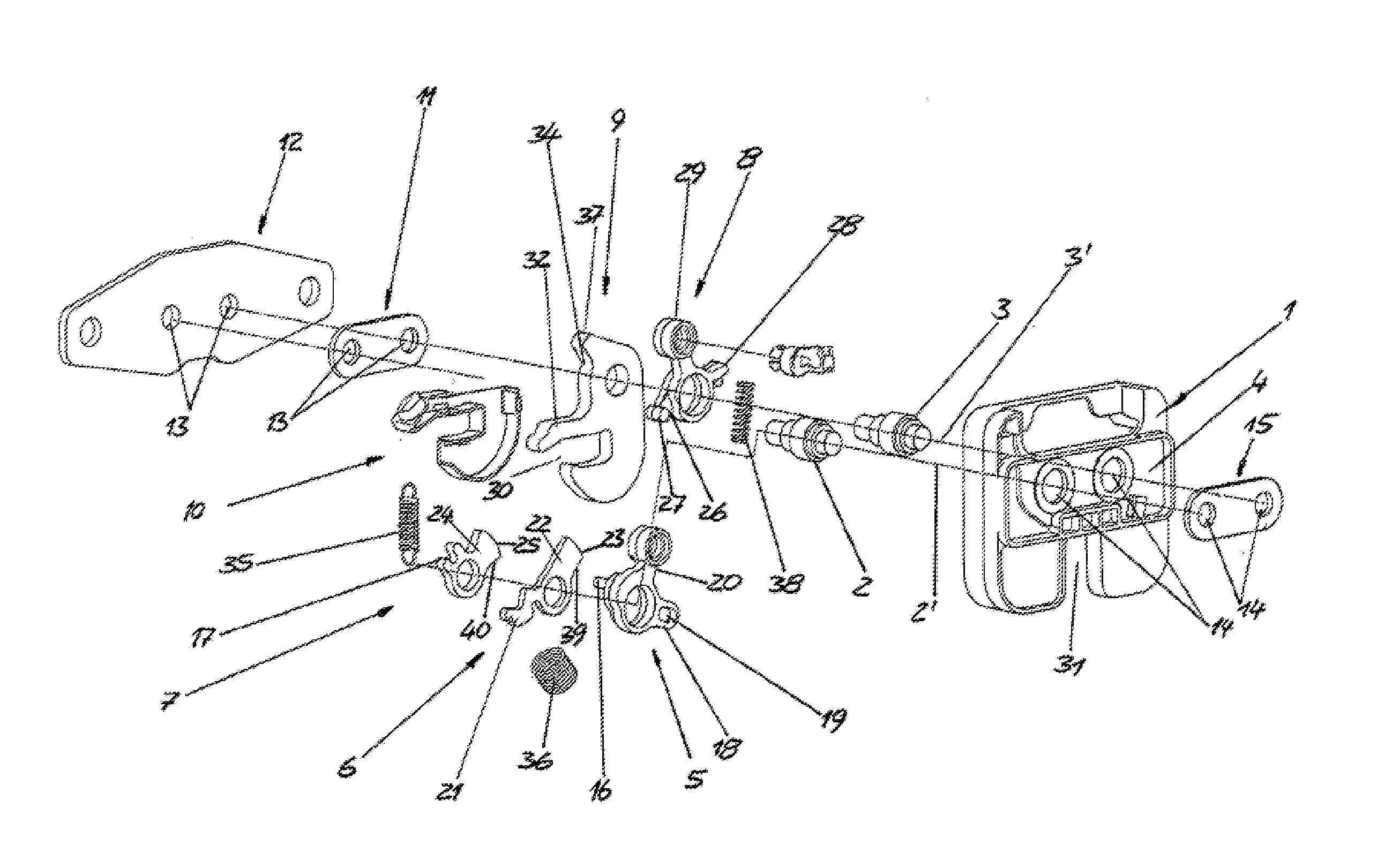
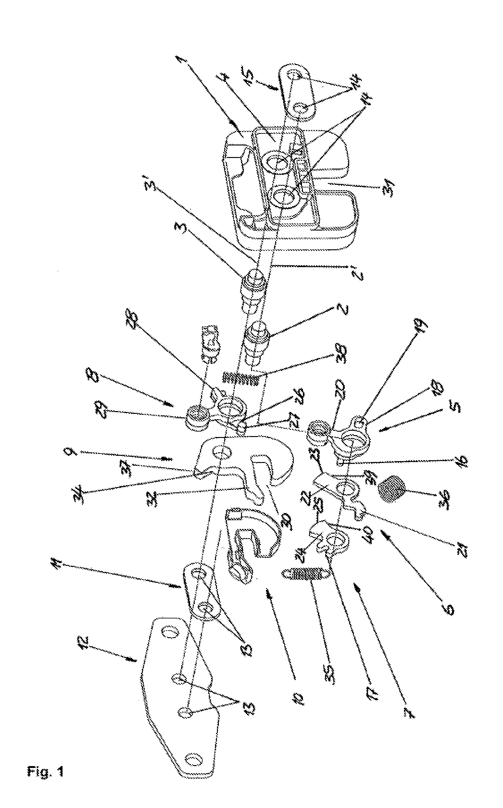
[0021]FIG. 1 shows an exploded illustration of a locking device,

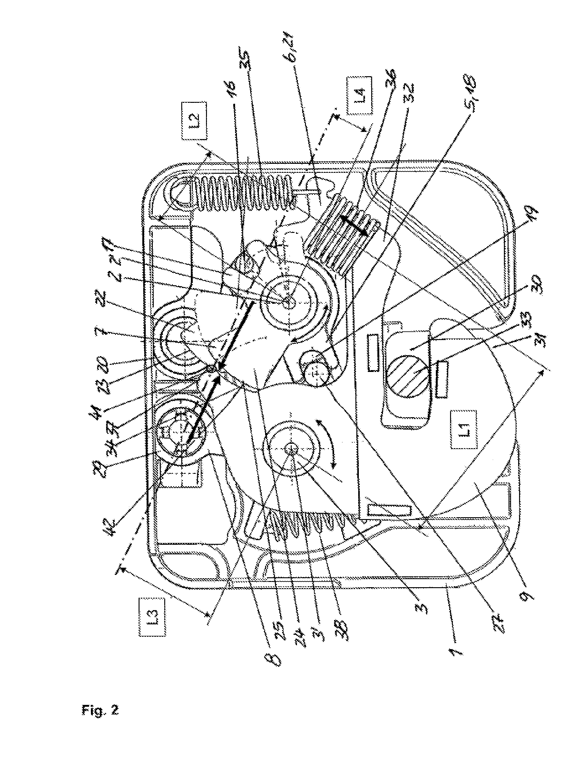
[0022]FIG. 2 shows a front-side inner view of the locking device according to FIG. 1 in the locked condition,

[0023]FIG. 3 shows a front-side inner view of the locking device according to FIG. 1 in the unlocked condition,

[0024]FIG. 4 shows a rear-side inner view of the locking device according to FIG. 1 in the locked condition, and

[0025]FIG. 5 shows a front-side inner view of the locking device according to FIG. 1 in the locked condition without a pawl.

[0026]The locking device which is shown is arranged in a floor region of a vehicle seat and has a cup-like housing 1, in which a first axle pin 2 and a second axle pin 3 are arranged fixedly parallel to one another so as to extend transvers...


PUM


Abstract

A locking device for a vehicle seat has a latch which is mounted pivotably about a second axis and is intended for locking a counter element, with a clamping eccentric which is mounted pivotably about a first axis parallel to the second axis and, by interaction with a first functional surface of the latch, secures a locked state of the latch. In the locked state, the clamping eccentric acts in a spring-loaded manner on the first functional surface via a clamping surface. The clamping eccentric is moveable from the locking position thereof into the unlocking position thereof. A pretensioned compression spring is provided, which is supported at one end thereof on an arm of the clamping eccentric in a manner spring-loading the latter into the locking position thereof and, at the other end thereof, acting upon the latch in the unlocking direction.

Description

[0001]The invention relates to a locking device for a vehicle seat having the features of the preamble of claim 1. The invention also relates to a vehicle seat having the features of claim 11.PRIOR ART[0002]One possibility for using locking devices of this type consists in serving to attach a vehicle seat to the floor in a motor vehicle.[0003]In the locked state, the clamping eccentric exerts a closing moment on the pawl via the clamping face.[0004]DE 10 2007 016 409 A1 has disclosed a locking device of this type for a vehicle seat, which locking device comprises a pawl and a clamping eccentric.[0005]US 2004 / 0 007 882 A1 discloses a locking device for a vehicle seat having a prestressed compression spring which acts with one end on an arm of the clamping eccentric and supports it in its locked location in a spring-loading manner.Object[0006]It is the object of the invention to provide a locking device of the type mentioned at the outset, which locking device requires a small amount ...

Claims


Application Information

Patent Timeline
Patent Type & Authority Applications(United States)
IPC IPC(8): B60N2/44B60N2/90
CPCB60N2/44B60N2/01583B60N2/366B60N2/90B60N2/919B60N2/015B60N2/36E05B17/00
Inventor MUELLER, PETERWINDECKER, VOLKERHABER, STEFANYASAROGLU, KADIRLABUK, SILKE
Owner KEIPER SEATING MECHANISMS CO LTD
Learn More