Exhaust gas purification system for engine

a technology of exhaust gas purification system and engine, which is applied in the direction of electrical control, separation processes, instruments, etc., can solve the problems of engine output reduction, engine output reduction, damage to dpf, etc., and achieve accurate estimation of the accumulation state of pm

Active Publication Date: 2014-10-16
MITSUBISHI HEAVY IND ENGINE & TURBOCHARGER LTD
View PDF7 Cites 1 Cited by
  • Summary
  • Abstract
  • Description
  • Claims
  • Application Information

AI Technical Summary

Benefits of technology

[0040]According to the present invention, it is possible to provide an exhaust gas purification system for an engine capable of accurately estimating the PM accumulation state and performing a

Problems solved by technology

However, as DPF has a limited capacity for collecting PM, excessive progress of accumulation of PM may result in decline in the performance of collecting PM or reduction in the engine output.
If the PM accumulation state is underestimated, the time to perform the regeneration treatment may be delayed, and thus the engine output may be reduce

Method used


Image

  • Exhaust gas purification system for engine
  • Exhaust gas purification system for engine
  • Exhaust gas purification system for engine

Examples


first embodiment

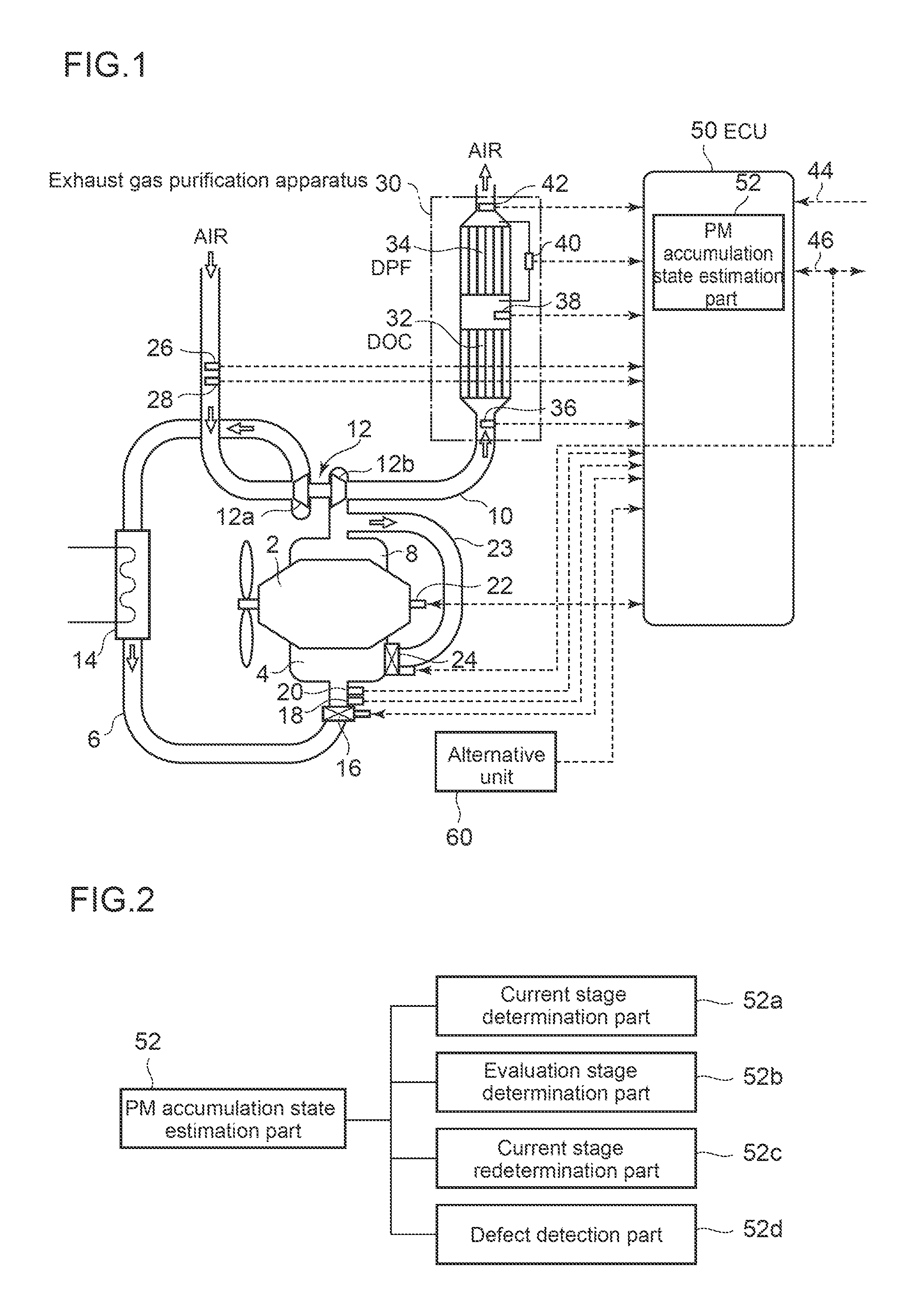
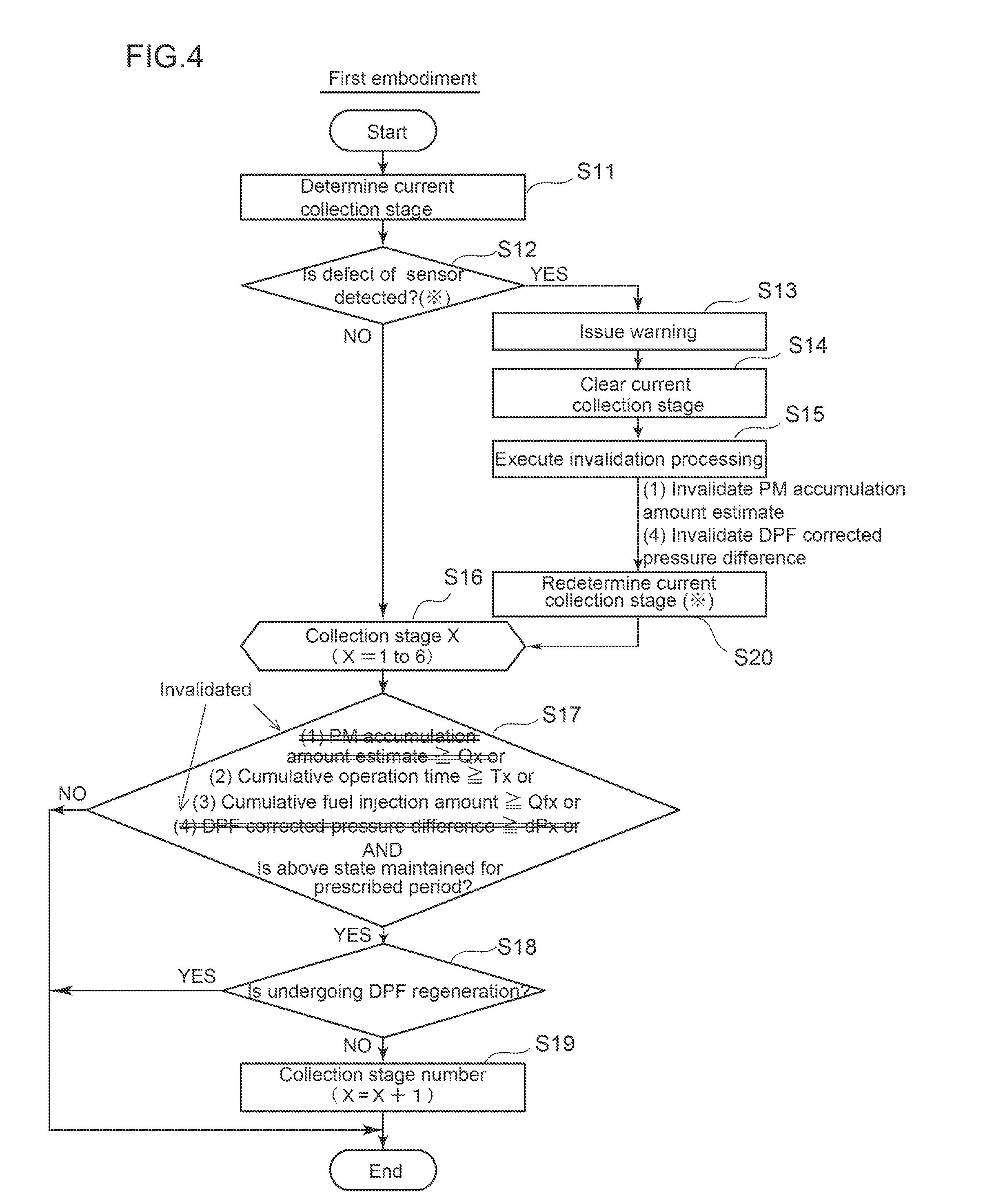
[0076]A behavior of the PM accumulation state estimation part 52 configured as above will be described with reference to the flowcharts shown in FIG. 4 to FIG. 6.

[0077]First, as illustrated in FIG. 4, in step S11, a current collection stage is determined by the above-described current stage determination part 52a. The current collection stage in step S11 is a collection stage which has been determined in the preceding cycle in the flowchart illustrated in FIG. 2 and is stored in the ECU 50.

[0078]Then, in step S12, detection determination is performed for the sensors by the above-described defect detection part 52d. That is, as illustrated in FIG. 6, whether a defect determination condition is satisfied is judged in step S31. Such judgment is made according to whether, in a case where the signal output from the sensor is a voltage signal, for example, the magnitude of the voltage falls within a prescribed range. Similarly, in a case where the signal output from the sensor is an elect...

second embodiment

[0091]In the above embodiment, an example of a case where defects of two sensors i.e. the DPF inlet temperature sensor 38 and the DPF outlet temperature sensor 42 are detected is described. In this second embodiment, an example of a case where a defect of the DPF differential pressure sensor 40 is detected will be described with reference to FIG. 8 to FIG. 10. In this embodiment, the essential constitution is the same as in the above embodiment, and the same elements as those of the above embodiment are assigned with the same reference numerals as those of the above embodiment, and the same description thereof will be omitted.

[0092]As illustrated in FIG. 10, the DPF pressure difference, which is an output value of the DPF differential pressure sensor 40, is a base for calculation of the DPF corrected pressure difference, which is one of the four evaluation indices. Thus, in this embodiment, as illustrated in FIG. 8 and FIG. 9, in step S20, the current evaluation stage is newly redet...

third embodiment

[0095]The third embodiment of the present invention will be described with reference to FIG. 11 to FIG. 13. In this embodiment, the essential constitution is the same as in the above embodiment, and the same elements as those of the above embodiment are assigned with the same reference numerals as those of the above embodiment, and the same description thereof will be omitted.

[0096]In the above-described embodiments, when a defect of a sensor is detected by the defect detection part 52d, the current evaluation stage is newly redetermined by the current stage redetermination part 52c, and whether to move up the current evaluation stage to the next rank is determined by the evaluation stage determination part 52b, by using an evaluation index other than an evaluation index based on an output value of the sensor of which a defect is detected.

[0097]However, the present invention is not limited thereto, and as illustrated in FIG. 11 to FIG. 13, it may be configured so that when a defect ...


PUM

PropertyMeasurementUnit
Temperatureaaaaaaaaaa
Pressureaaaaaaaaaa
Flow rateaaaaaaaaaa

Abstract

An exhaust gas purification system of engine configured to classify a PM accumulation state of DPF into multiple evaluation stages based on a plurality of evaluation indices, and to repeatedly perform determination of the current evaluation stage by the current stage determination part and determination of whether to move up the current evaluation stage to the evaluation stage of the next rank by the evaluation stage determination part, wherein upon a defect of a sensor among different types of sensors being detected by the defect detection part, the current evaluation stage is newly redetermined by the current stage redetermination part as substituted for the current evaluation stage determined by the current stage determination part.

Description

TECHNICAL FIELD [0001]The present invention relates to an exhaust gas purification system for an engine provided with a DPF, particularly to a technique of controlling a timing of combustion removal of PM accumulated in the DPF.BACKGROUND ART[0002]As a technique effective for removing particulate matter (exhaust particulate, hereinafter referred to as PM) contained in an exhaust gas of a diesel engine, a diesel particulate filter (hereinafter referred to as DPF) is known. DPF is a device for collecting PM employing a filter. DPF is provided on an exhaust passage of an engine, and is a device for collecting PM including soot exhausted from the engine with a filter and removing PM from the exhaust gas. A part of PM collected by the DPF will be combusted by a high-temperature exhaust gas exhausted from the engine during operation, but the remainder of the PM will be accumulated in the filter of the DPF. However, as DPF has a limited capacity for collecting PM, excessive progress of acc...

Claims


Application Information

Patent Timeline
IPC IPC(8): B01D53/94
CPCF01N9/002F01N11/00F01N2550/00F01N2560/06F01N2560/07B01D53/94F01N2900/0412F02D41/029F02D41/222F02D2200/0812Y02T10/47F01N2560/08F01N2550/04F01N2900/1606F01N2900/0416F01N2900/08Y02T10/40B01D46/00B01D53/86B01D53/92F01N3/023F01N3/18F01N3/24
Inventor TAKAYANAGI, KOOKUDA, KEISUKESASE, RYO
Owner MITSUBISHI HEAVY IND ENGINE & TURBOCHARGER LTD
Why Eureka
Try Eureka