Modular concrete form panel

a concrete form and module technology, applied in the direction of walls, thin material handling, constructions, etc., can solve the problems of high labor intensity, high labor intensity, and burdensomeness of assembling the initial concrete formwork, and achieve the effect of reducing labor intensity, costing a lot of time, and reducing labor intensity

Inactive Publication Date: 2014-10-16
GADDES SHANE
View PDF8 Cites 11 Cited by
  • Summary
  • Abstract
  • Description
  • Claims
  • Application Information

AI Technical Summary

Benefits of technology

[0009]In some embodiments, the present invention provides a modular form panel for assembling concrete structures. The modular form panels of the present invention include inner and outer panel sections separated by a filling gap. One or more support ties span the filling gap and provide a load-bearing function to prevent the panel sections from separating when concrete is poured into the filling gap. Concrete poured into the filling gap provides a concrete wall or roof section. The outer panel section includes the side of the panel that is oriented toward the exterior of the structure, and the inner panel section includes the side of the panel that is oriented toward the interior of the structure. In some embodiments, the outer panel section includes a foam material such as but not limited to expanded polystyrene foam (EPS). The outer panel section serves both a thermally insulative function as well as provides a protective sheathing covering the concrete wall or roof portions of the structure.

Problems solved by technology

One problem associated with such conventional removable formwork concrete building devices and methods includes the amount of labor and time required to assemble the initial concrete formwork.
This is especially burdensome for forming complex architecture and curved members.
These tasks are time-consuming, costly, and very labor-intensive.
The problems associated with conventional removable formwork concrete construction methods and devices are even more pronounced on smaller scale construction projects, such as residential home construction, where overall project budgets generally do not accommodate the labor and cost intensive procedures associated with formwork assembly.
Conventional masonry blocks of this nature, however, are also very time-consuming and require significant labor to construct at a building site.
Additionally, the generally standardized shape of the blocks limits the variety of building architecture that can be assembled using the blocks.
The pre-cast structures are very heavy and must be installed using heavy machinery such as overhead cranes.
These types of concrete construction systems are also very labor intensive and expensive to implement.
Like pre-cast systems, tilt-up systems are very labor intensive and expensive to implement.

Method used


Image

  • Modular concrete form panel
  • Modular concrete form panel
  • Modular concrete form panel

Examples


Embodiment Construction

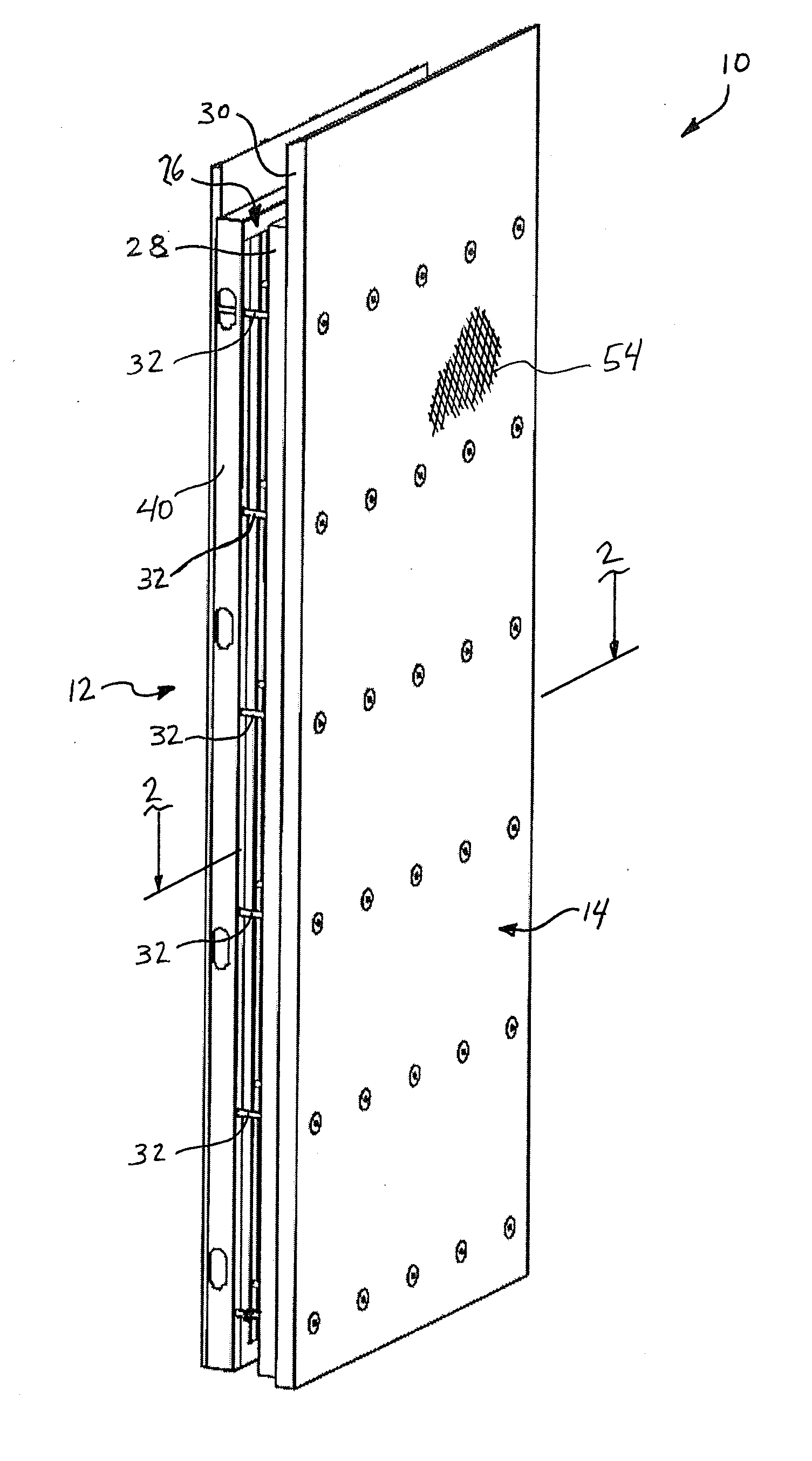
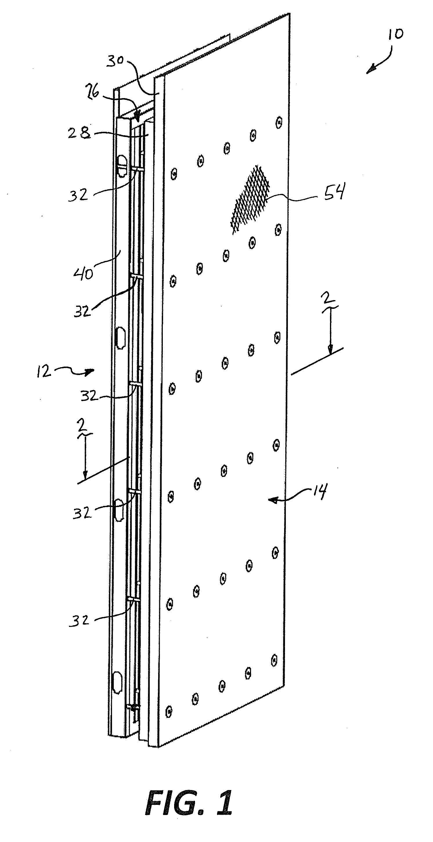
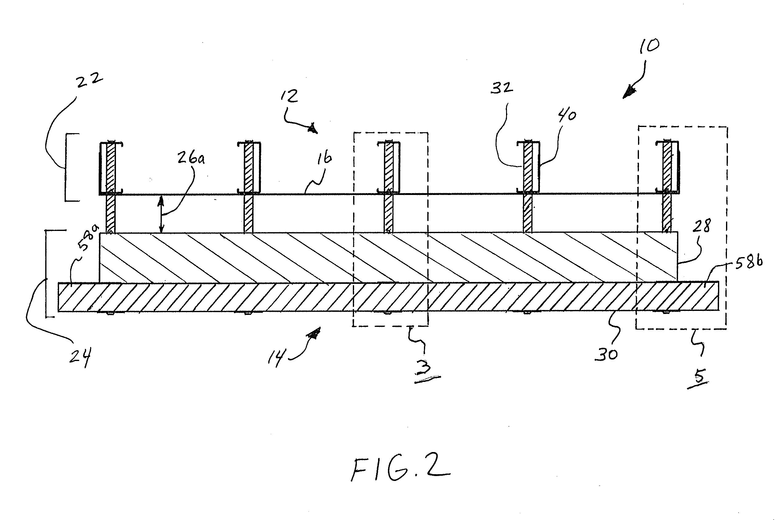
[0029]Referring now to the drawings, an embodiment of a modular form panel is generally illustrated in FIG. 1 and is designated by the numeral 10. Modular form panel 10 includes an inner side 12 and an outer side 14. Inner side 12 may be referred to as an inner panel section 12. Outer side 14 may also be referred to as an outer panel section 14. Panel 10 provides a modular component that can be combined with additional panels to form a form for pouring concrete at a construction location. A filling gap 26 is defined between the inner and outer sides 12, 14. Filling gap 26 defines a void between inner and outer sides 12, 14 into which concrete may be poured. Inner and outer sides 12, 14 provide containment for concrete that is poured into filling gap 26. Filling gap 26 defines a filling gap width 26a, seen in FIG. 2. Filling gap width 26a may vary in different embodiments of modular form panel 10 to provide desired concrete thicknesses between inner and outer sides 12, 14.

[0030]Modul...


PUM


Abstract

A modular form panel for assembling a cast-in-place concrete structure includes an inner panel section and an outer panel section. A filling gap is defined between the inner and outer panel sections. The filling gap is configured to receive concrete poured on-site to form a concrete wall or roof section. One or more tie members span the filling gap interconnecting the inner and outer panel sections. The panel includes an integral side flange in some embodiments. When multiple panels are positioned adjacent one another, the adjacent side flanges form an end gap on each lateral side of the panel. The end gap has a thickness greater than the filling gap thickness. Concrete disposed in each end gap forms an integrated support column on each side of the panel. A bond beam gap is defined along the top edge of the panel having a greater thickness than the filling gap.

Description

CROSS-REFERENCES TO RELATED APPLICATIONS[0001]This application claims domestic priority to U.S. Provisional patent application No. 61 / 783,057 filed Mar. 14, 2013, all of which is hereby incorporated by reference in its entirety.[0002]A portion of the disclosure of this patent document contains material that is subject to copyright protection. The copyright owner has no objection to the reproduction of the patent document or the patent disclosure, as it appears in the U.S. Patent and Trademark Office patent file or records, but otherwise reserves all copyright rights whatsoever.BACKGROUND[0003]The present invention relates generally to concrete forms for building structures and more particularly to cast-in-place construction form panels and associated structures, devices and methods.[0004]Removable form work devices are generally known in the art for casting concrete structures. When erecting structures made of concrete using conventional methods, workers typically assemble a form or...

Claims


Application Information

Patent Timeline
Patent Type & Authority Applications(United States)
IPC IPC(8): E04B5/02
CPCE04C2/50E04B2/86E04B1/16E04B1/161E04B1/165E04B2/8647Y10T428/249923
Inventor GADDES, SHANEWOOLVERTON, STEPHENWESTERLUND, ROBERT
Owner GADDES SHANE
Why Eureka
Try Eureka