
Methods and systems for displaying procedure information on an aircraft display

a technology for aircraft display and procedure information, applied in the field of aviation, can solve the problems of increasing/decreasing the time, fuel and operational cost required to fly the procedure, and the impact overall flight operational cost, so as to reduce one or more of fuel consumption, flight time, or overall flight operational cost

Active Publication Date: 2014-10-16
HONEYWELL INT INC
View PDF4 Cites 14 Cited by
  • Summary
  • Abstract
  • Description
  • Claims
  • Application Information

AI Technical Summary

Benefits of technology

The patent describes a system and method for displaying information on a screen to help aircrew members navigate an aircraft. The system includes a map that moves to match the aircraft's movement, sensors to detect the current location of the aircraft, and a computer program to analyze the flight path and select the best route for the aircraft. The computer program also displays a visual representation of the selected flight path on a moving map, which is meant to help the pilot pilot the aircraft more safely and efficiently.

Problems solved by technology

One limitation of such a system is the fact that the procedures that are illustrated on a paper-based chart (and, consequently depicted on a moving map display) are generic and do not reflect real-time conditions experienced by the aircraft, such as environmental conditions (e.g., altitude, wind speed, wind direction, etc.), geographic conditions (e.g., terrain, obstructions, etc.), or airspace conditions (e.g., air traffic congestion on departure, arrival, or en route procedures, temporary flight restrictions, etc.) that are experienced by the aircraft as it flies the procedure.
Such environmental, geographic, and airspace conditions can have a substantial impact on the time, fuel, and operational cost required to fly the procedure.
For example, a tail wind or a head wind may increase or diminish the distance that will actually be traveled by an aircraft when following the published procedure, thus increasing / decreasing the time, fuel, and operational cost required to fly the procedure.

Method used


Image

  • Methods and systems for displaying procedure information on an aircraft display
  • Methods and systems for displaying procedure information on an aircraft display
  • Methods and systems for displaying procedure information on an aircraft display

Examples


Embodiment Construction

[0015]The following detailed description is merely exemplary in nature and is not intended to limit the invention or the application and uses of the invention. As used herein, the word “exemplary” means “serving as an example, instance, or illustration.” Thus, any embodiment described herein as “exemplary” is not necessarily to be construed as preferred or advantageous over other embodiments. All of the embodiments and implementations of the systems and methods for displaying procedure information described herein are exemplary embodiments provided to enable persons skilled in the art to make or use the invention and not to limit the scope of the invention, which is defined by the claims. Furthermore, there is no intention to be bound by any expressed or implied theory presented in the preceding technical field, background, brief summary, or the following detailed description.

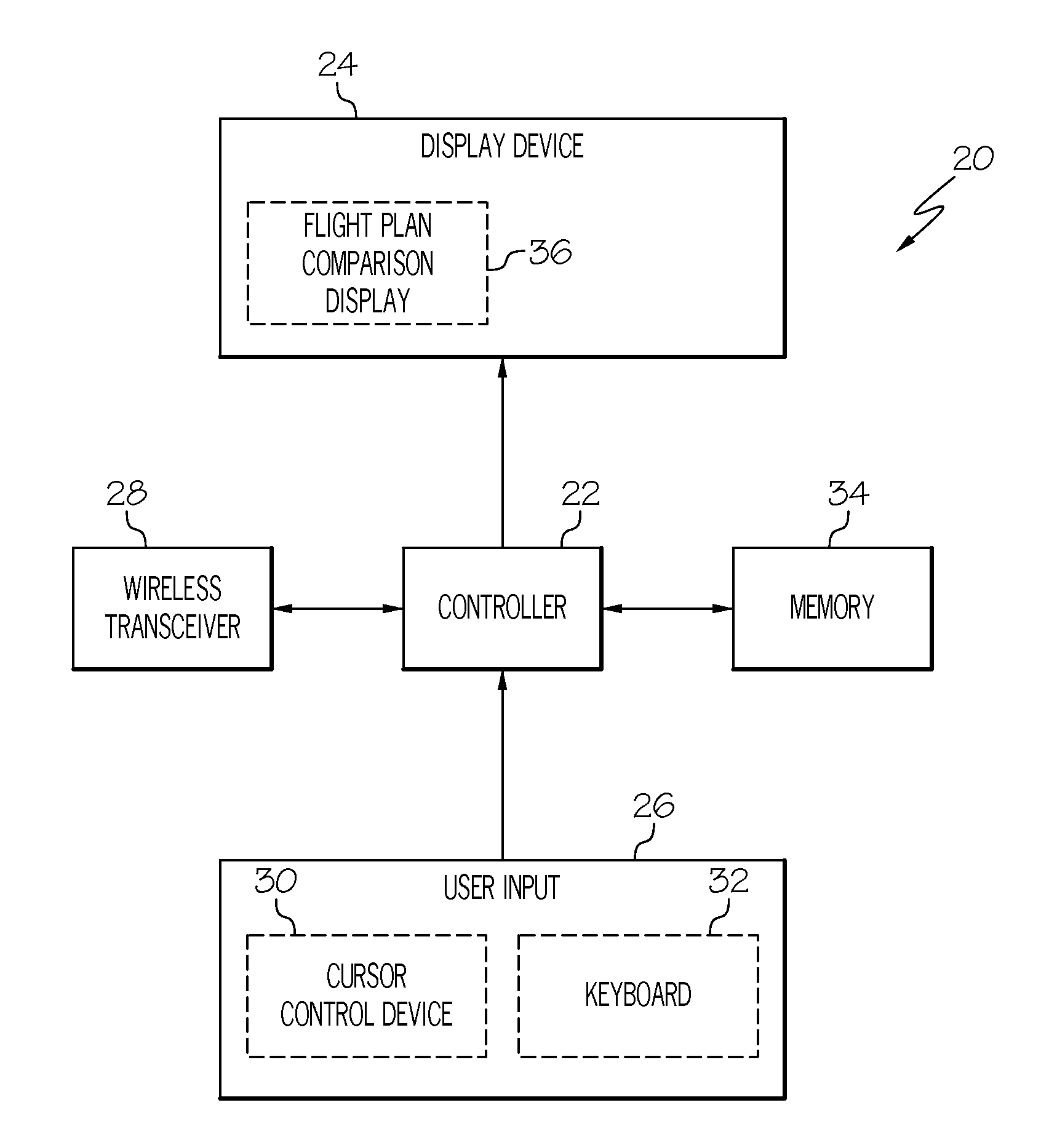
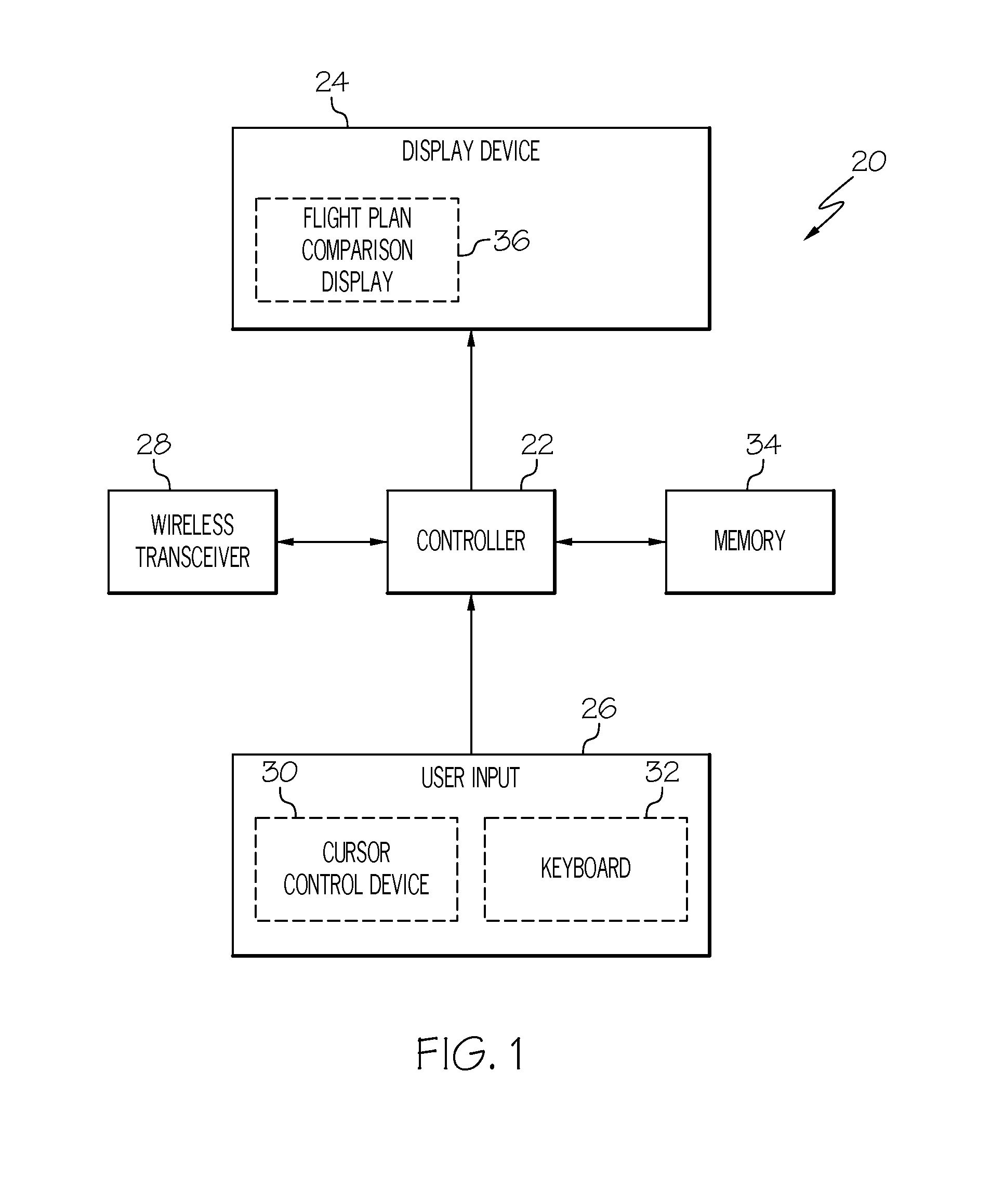
[0016]FIG. 1 is a generalized block diagram of flight plan analysis system 20 suitable for deployment on an ...


PUM


Abstract

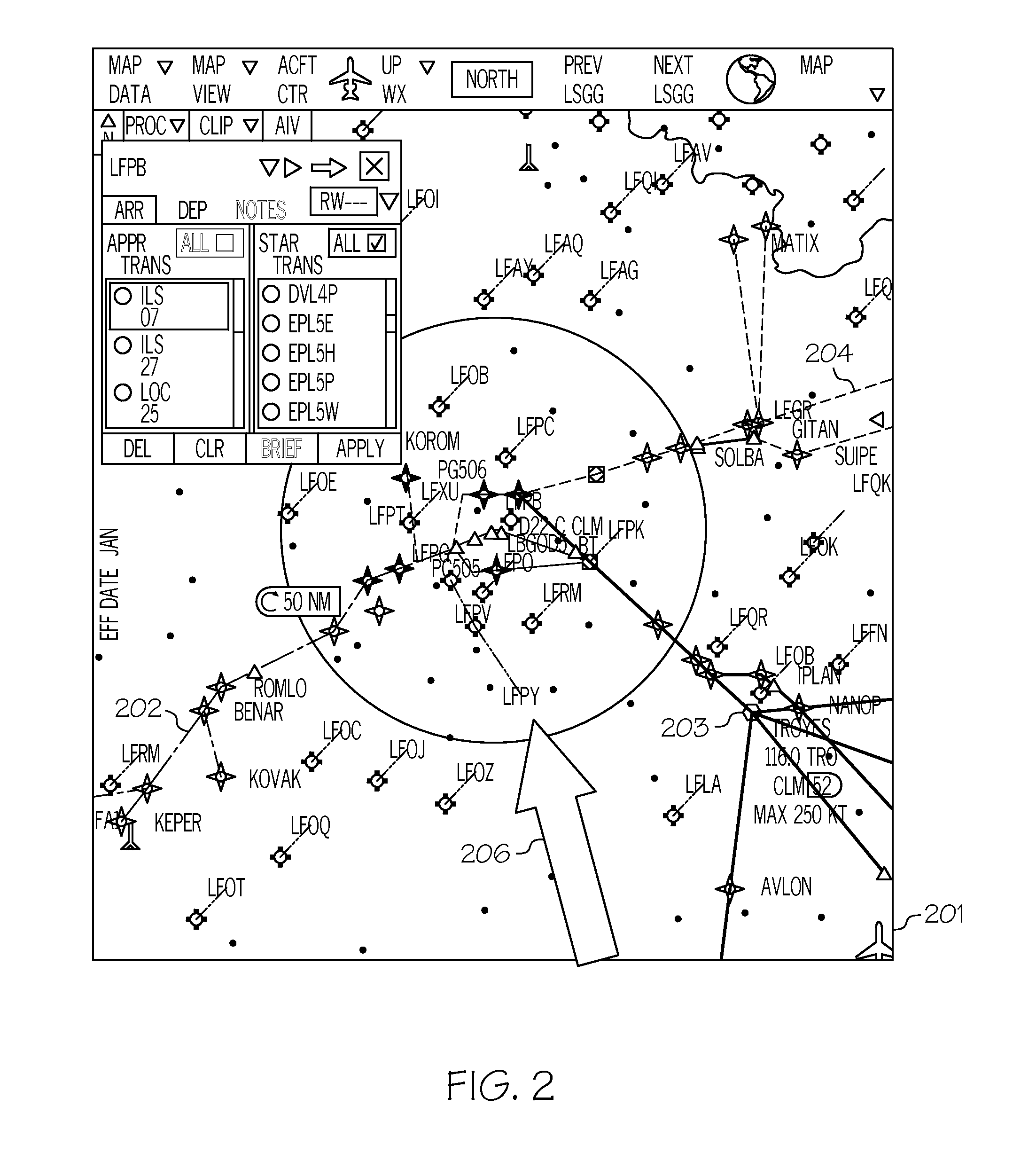
A method for displaying a flight path navigational procedure includes, but is not limited to, detecting with a position detecting system a current location of the aircraft, obtaining from an electronic storage device a plurality of flight path navigation procedures available for a geographic location, determining with a flight path analysis system a preferred flight path that will be taken by the aircraft, and displaying on a display unit a moving map corresponding with the current location of the aircraft and further displaying a depiction of the plurality of flight path navigation procedures on the moving map. The preferred flight path is displayed with a visual cue that visually differentiates the preferred flight path from the other flight paths of the plurality of flight path navigation procedures.

Description

TECHNICAL FIELD[0001]The present invention generally relates to aviation, and more particularly relates to systems and methods for displaying procedure information on an aircraft display.BACKGROUND[0002]Paper-based charts have been used for decades to assist a pilot and / or other members of an aircrew with navigation of an aircraft. Paper-based charts (which also include PDF files depicting such charts) contain navigation procedures that an aircraft is required to follow at various stages throughout a flight. A procedure is a maneuver that an aircraft is required to undertake when it reaches a predetermined position. For example, a paper-based chart may include a depiction of a flight path together with annotations that indicate the course and the altitude that an aircraft is required to fly and maintain when approaching an airfield for landing. Another example would include the courses and altitude an aircraft may be required to fly and maintain while in a holding pattern above an a...

Claims


Application Information

Patent Timeline
Patent Type & Authority Applications(United States)
IPC IPC(8): B64D45/00
CPCB64D45/00G08G5/0021G08G5/0039G08G5/0078G08G5/0086G08G5/0091G08G5/025
Inventor BURGIN, ROGER W.MALVIYA, PRAMOD KUMARPEPITONE, DAVEBALL, JERRY
Owner HONEYWELL INT INC
Learn More