
Method, apparatus, and system used for purifying and silencing exhaust of internal combustion engine

a technology of internal combustion engine and exhaust gas, which is applied in the direction of engines, mechanical equipment, machines/engines, etc., can solve the problems of poor muffling effect of existing mufflers, poor ventilation conditions of two-stroke diesel engines, and often sparks from chimneys, so as to facilitate nox purification and release or reduce spa

Inactive Publication Date: 2014-10-23
PENG SIGAN
View PDF8 Cites 3 Cited by
  • Summary
  • Abstract
  • Description
  • Claims
  • Application Information

AI Technical Summary

Benefits of technology

The present invention provides a new solution for purifying and muffling exhaust gas from an internal combustion engine. The device achieves purification and muffling effects simultaneously, and can also save energy or recover residual heat. It can replace existing mufflers and residual heat boilers, providing sufficient space for purifying exhaust gas more comprehensively. The method involves expanding the exhaust gas and allowing it to come into contact with scrubbing water which can absorb SO2 and muffle noise. The purified exhaust gas and residual heat can be saved or recovered for use in other applications. The device can be installed in the position where the existing muffler is located. Overall, the invention provides a single solution for achieving purification, muffling, and energy recovery in a compact space.

Problems solved by technology

Modern large and medium sized diesel engines, especially two-stroke diesel engines with poor ventilation conditions, often produce sparks from chimneys, usually called the flaming chimney.
Marine diesel engine flaming chimney will not only result in a fire but also endanger the safety of oil tankers.
The problem is that the process and structure of the existing muffler not only has poor muffling effect, but also does not reduce the temperature of the hot fuel gas, so that sparks are not completely extinguished, which is always a security risk of the oil tanker.
The applicant found that during the implementation of the invention, due to space constraints of the existing vessel structure, it is hard to implement the invention on an existing vessel.
Current vessels barely have sulfur oxides cleaning device installed thereon, on one hand this is because the international legislation on limitation of internal combustion engine sulfur oxides emissions has only progressively introduced from 2005, and on the other hand, this is also due to space limitations in the existing vessels' structures, so that it is almost impossible to install sulfur oxides cleaning devices that need to occupy a larger space.
Both of the cleaner and seawater processor require larger space.
The arrangement of the seawater processer is rather flexible, while the exhaust gas cleaner must be disposed in the exhaust passage of the internal combustion engine, and therefore a larger residual space is needed in the exhaust passage of the internal combustion engine along the way, which is a conflict to configuration of almost all offshore platforms because the internal combustion engine exhaust passage along the way happens to be the most crowded area of the space.
For future new construction of offshore platforms, leaving space for the exhaust gas cleaning device means an increase in operating costs.
For those large number of underway vessels who in recent years face the difficult conditions of implementation of international legislation on purification of sulfur oxides, they do not have (and impossibly have) reserved space for installing exhaust gas cleaning device during the initial construction.
However, along with progressive implementation of the international legislation on the restriction of sulfur oxide emissions from internal combustion engines such as vessels in 2005, the purification of sulfur oxides from the internal combustion engine such as that used in vessels has become unavoidable, therefore there is an urgent need to provide a purification and muffling device and method for exhaust gas from an internal combustion engine, which can be used in offshore platforms such as vessels with limited space.
It has been already difficult when only desulfurization equipment is added in the existing vessel structure.
It would be harder to further add an apparatus for purifying NOx in the existing technology.
In sum, it can be seen that, space limitations is the constraint of applying seawater scrubbing purification process to offshore platforms such as vessels.

Method used


Image

  • Method, apparatus, and system used for purifying and silencing exhaust of internal combustion engine
  • Method, apparatus, and system used for purifying and silencing exhaust of internal combustion engine
  • Method, apparatus, and system used for purifying and silencing exhaust of internal combustion engine

Examples


first embodiment

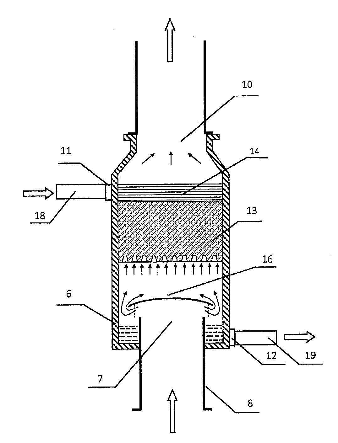
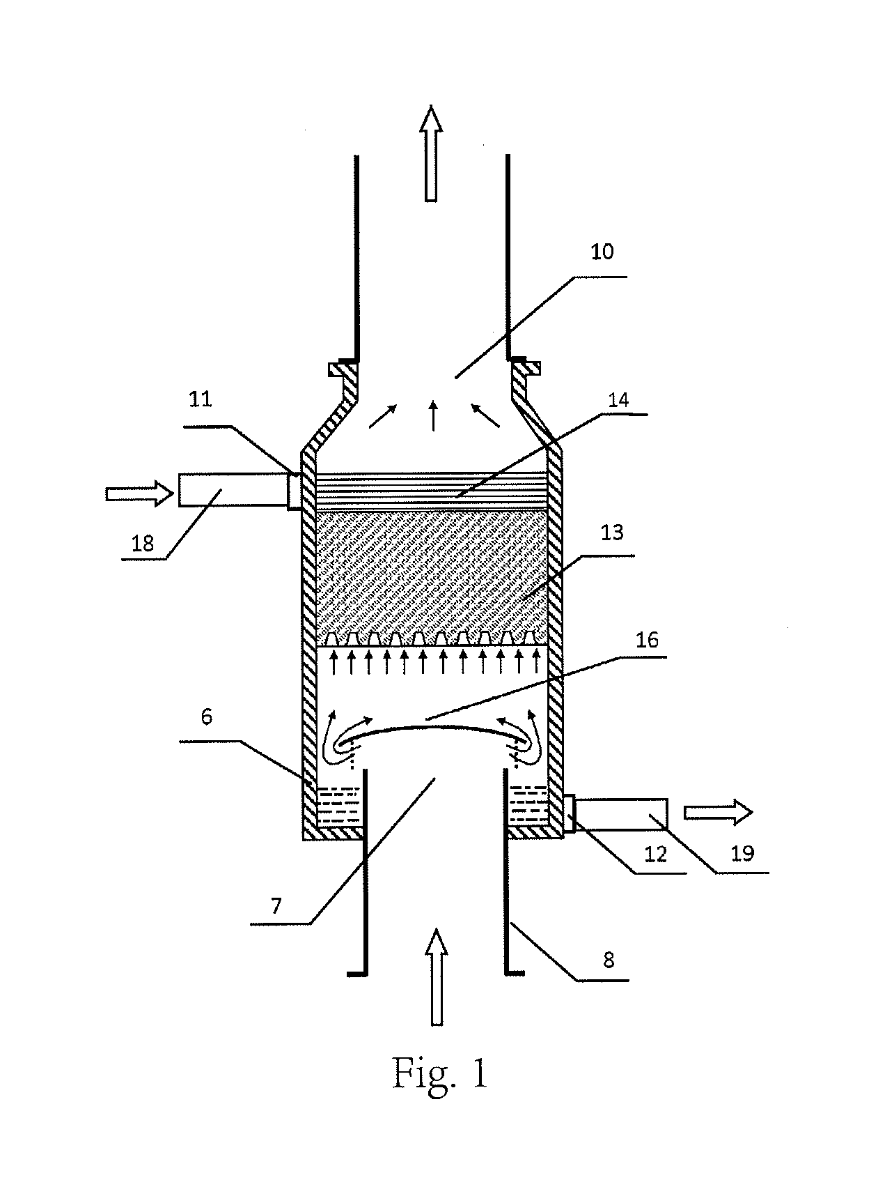
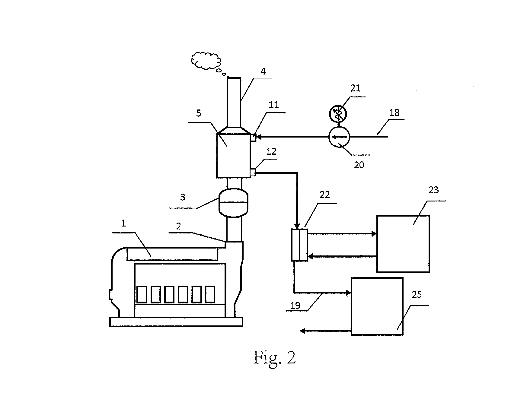
[0070]FIG. 1 and FIG. 2 show the device and system for purifying and muffling exhaust gas from an internal combustion engine according the present invention.

[0071]As shown in FIG. 1, the device for purifying and muffling exhaust gas from an internal combustion engine of the embodiment includes a housing 6 provided with a scrubbing water inlet 11 and a scrubbing water outlet 12, wherein the scrubbing water inlet 11 is located on the upper part of the side surface of the housing and the scrubbing water outlet 12 is located on the lower part of the side surface of the housing. Under the gravity effect, the seawater entering the housing via the scrubbing water inlet 11 passes through from top to bottom and is discharged via the scrubbing water outlet 12.

[0072]The housing is also provided with an exhaust gas inlet pipe 8 and an exhaust gas outlet 10, wherein the exhaust gas inlet pipe 8 extends into the interior of the housing, and the pipe orifice extending to the inside of the housing ...

second embodiment

[0081]FIG. 3 shows the device for purifying and muffling exhaust gas from an internal combustion engine according to the present invention.

[0082]Different from the device for purifying and muffling exhaust gas from an internal combustion engine of the first embodiment, the exhaust gas inlet 7 of the device for purifying and muffling exhaust gas from an internal combustion engine in this embodiment is located at the lower part of the side surface of the housing 6. In a gravity direction, the position of the exhaust gas inlet 7 is higher than the position of the scrubbing water outlet 12. In this case, the exhaust passage of the internal combustion engine communicates with the side surface of the housing via the exhaust gas inlet pipe 8. Since the exhaust gas enters from the side surface of the housing, a water baffle is unnecessary. The scrubbing water of the present embodiment reuses the engine cooling water.

[0083]The exhaust passage of the internal combustion engine communicates wi...

third embodiment

[0084]FIG. 4 and FIG. 5 show the device and system for purifying and muffling exhaust gas from an internal combustion engine of the present invention.

[0085]Different from the device for purifying and muffling exhaust gas from an internal combustion engine of the first embodiment, in this embodiment, a cooling pipeline 17 is provided in the housing of the device for purifying and muffling exhaust gas from an internal combustion engine, i.e. the pipeline encapsulating the second cooling water. The cooling pipeline 17 is located below the water baffle 16, so that the scrubbing water does not fall onto the cooling pipeline 17, thereby producing high temperature steam. The inlet and outlet of the cooling pipeline 17 respectively extend out of the housing 6, and the inlet is higher than the outlet in the direction of gravity. When the device is installed, the inlet and outlet are connected to the pipeline transporting fluids. As a variation of this embodiment, the inlet and outlet of the ...


PUM


Abstract

A method for purifying and muffling exhaust gas from an internal combustion engine, comprising the following steps: 1) allowing exhaust gas discharged by the internal combustion engine to enter into the interior of a housing (6) via an exhaust gas inlet (7) of the housing (6), wherein abrupt expansion of cross section occurs from the exhaust gas inlet (7) to the interior of the housing (6); 2) allowing scrubbing water which can absorb SO2 to enter via a scrubbing water inlet (11), and allowing the exhaust gas in the interior of the housing and the scrubbing water to come into contact with each other, then discharging the scrubbing water via a scrubbing water outlet (12) of the housing; and 3) discharging the exhaust gas via an exhaust gas outlet (10) of the housing. The method simultaneously produces effects of purifying SO2, muffling and saving energy, and eliminates sparks in the exhaust gas. A device and system for purifying and muffling exhaust gas from an internal combustion engine are also provided.

Description

FIELD OF THE INVENTION[0001]The present invention relates to a method for purifying and muffling exhaust gas from an internal combustion engine and, in particular, to a method of purifying sulfur dioxide (SO2) in the exhaust gas or purifying sulfur dioxide (SO2) and nitrogen oxides (NOx) synchronously while highly efficiently and safely decreasing the noise of the exhaust gas from the internal combustion engine. The invention also relates to a device and system for purifying and muffling exhaust gas from an internal combustion engine. The method, device and system provided by the invention are especially suitable for, but not limited to, offshore platforms such as vessels, drillings and floating factories, etc.DESCRIPTION OF THE PRIOR ART[0002]Modern large and medium sized diesel engines, especially two-stroke diesel engines with poor ventilation conditions, often produce sparks from chimneys, usually called the flaming chimney. The flaming chimney effect of a diesel engine is usual...

Claims


Application Information

Patent Timeline
IPC IPC(8): F01N1/02
CPCF01N1/02F01N3/04F01N1/082F01N2230/06F01N2570/04F01N2590/02Y02T10/12
Inventor PENG, SIGAN
Owner PENG SIGAN
Learn More