Method for manufacturing a braking element with integrated sensor, in particular a brake pad, brake pad with integrated sensor, vehicle braking system and associated method

a technology of integrated sensors and brake pads, which is applied in the direction of friction linings, instruments, force/torque/work measurement apparatus, etc., can solve the problems of premature and often unnecessary replacement of brake pads, inability to detect and/or predict the occurrence of many, and inability to manufacture brake pads. the effect of avoiding abnormal brake pad consumption, significant energy saving and better control over braking conditions

Active Publication Date: 2014-10-23
ITT ITAL SRL
View PDF10 Cites 51 Cited by
  • Summary
  • Abstract
  • Description
  • Claims
  • Application Information

AI Technical Summary

Benefits of technology

[0023]For example, if the vehicle braking system has not been activated but the central processing unit nonetheless receives a signal from one or more sensors, it can be established that the braking element, for example a brake pad, is “touching” the element to be braked, for example a brake disc carried by the wheel of the vehicle. It would then be possible according to the invention to either activate a warning device to alert the user of the abnormality, an abnormality that can be eliminated by a simple mechanical adjustment of the brake calipers for example, or else to automatically intervene upon the braking element actuating mechanism (piston or caliper) so as to retract the braking element with respect to the element being braked. Abnormal brake pad consumption is thus avoided and significant energy savings obtained in driving the vehicle.
[0024]A further advantage consists in the fact that, by suitably processing the signal emitted by a plurality of sensors applied to a single braking element according to an array pattern it is possible to detect any vibration and / or abnormal distribution of contact pressure between the brake pad and disc which induce differential wear and / or noises and squeaks. As these conditions usually occur as a result of abnormal pressure distribution and / or of the application of discrete values of contact pressure, it is thereby possible to rebalance the distribution of pressure or in some cases to detect the pressure which triggered the phenomenon and to operate the braking system, for example by acting upon the actuating mechanism of the braking element with the integrated sensor, so as to thereby avoid the application of the pressures that induce said phenomenon, for example by applying higher or lower pressures depending on the driving conditions.
[0025]By elaborating the signal from more piezoceramic sensors, i.e. from a set of discrete sensors formed by a plurality of independent piezoceramic sensors at least one of which is designed to react to forces that are transverse to the direction of the pressure applied by the braking element, having been polarized in a direction perpendicular to the polarization direction of the other piezoceramic sensors, it will then be possible to calculate the instantaneous coefficient of friction between the brake pad with the integrated sensor and the disc. With this value being transmitted to the vehicle on-board computer, and it being combined in real time with signals from other systems (ABS, ESP, etc.), this will allow for better control over braking conditions and consequently the stopping distance of the vehicle.

Problems solved by technology

With the vehicle braking systems currently in production, there is no way to detect while using the vehicle, if not by way of external systems, the forces that are exchanged between the brake pads (or brake shoes for vehicles equipped with drum brakes) and the disc or drum element attached to the wheel that is being braked.
This makes it impossible to detect and / or predict the occurrence of many drawbacks which can vary from abnormal brake pad wear due for example to the pads “touching” the disc even when braking is not taking place due to poor caliper adjustment, rather than the noise, vibration and undesirable squealing during braking.
These problems can lead to malfunctions or even to premature and often unnecessary brake pad replacement.
The same study points out however that the system described should be considered as a design aid tool and not as a system suitable for use in the mass production of brake pads.
It should be noted in fact that at the moment it is considered to be extremely difficult, if not impossible, to have piezoelectric sensors in the vicinity of brake pads or on the brake pads themselves, due to the high temperatures and pressures to which brake pads are subjected during the production process or that are developed during braking, resulting in temperatures and pressures that are incompatible with most known piezoelectric sensors.
These systems, which are based on the variation in capacitance or electrical resistance of a sensor or an entire functional layer are however very difficult to be made feasible in practice, because, on one hand they allow for relatively precise measurement of forces applied in static manner or in a very slow acting manner, but they are unable to detect rapid changes in force such as those that occur during braking; and, on the other hand, they also need to be continuously electrically supplied thus leading to associated energy consumption and considerably complicated construction in that electrical energy has to be supplied to relatively fast moving parts.

Method used


Image

  • Method for manufacturing a braking element with integrated sensor, in particular a brake pad, brake pad with integrated sensor, vehicle braking system and associated method
  • Method for manufacturing a braking element with integrated sensor, in particular a brake pad, brake pad with integrated sensor, vehicle braking system and associated method
  • Method for manufacturing a braking element with integrated sensor, in particular a brake pad, brake pad with integrated sensor, vehicle braking system and associated method

Examples


Embodiment Construction

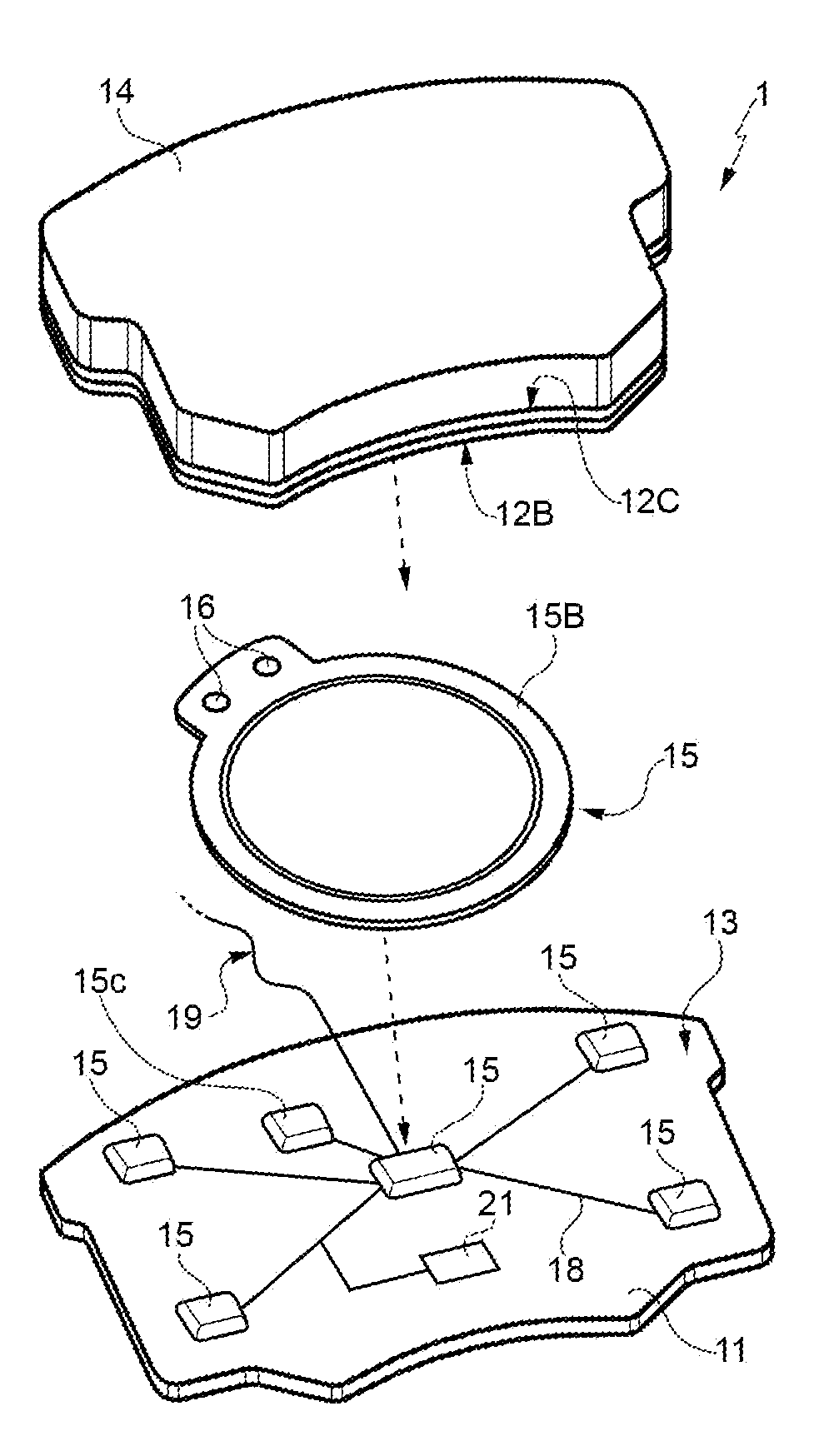
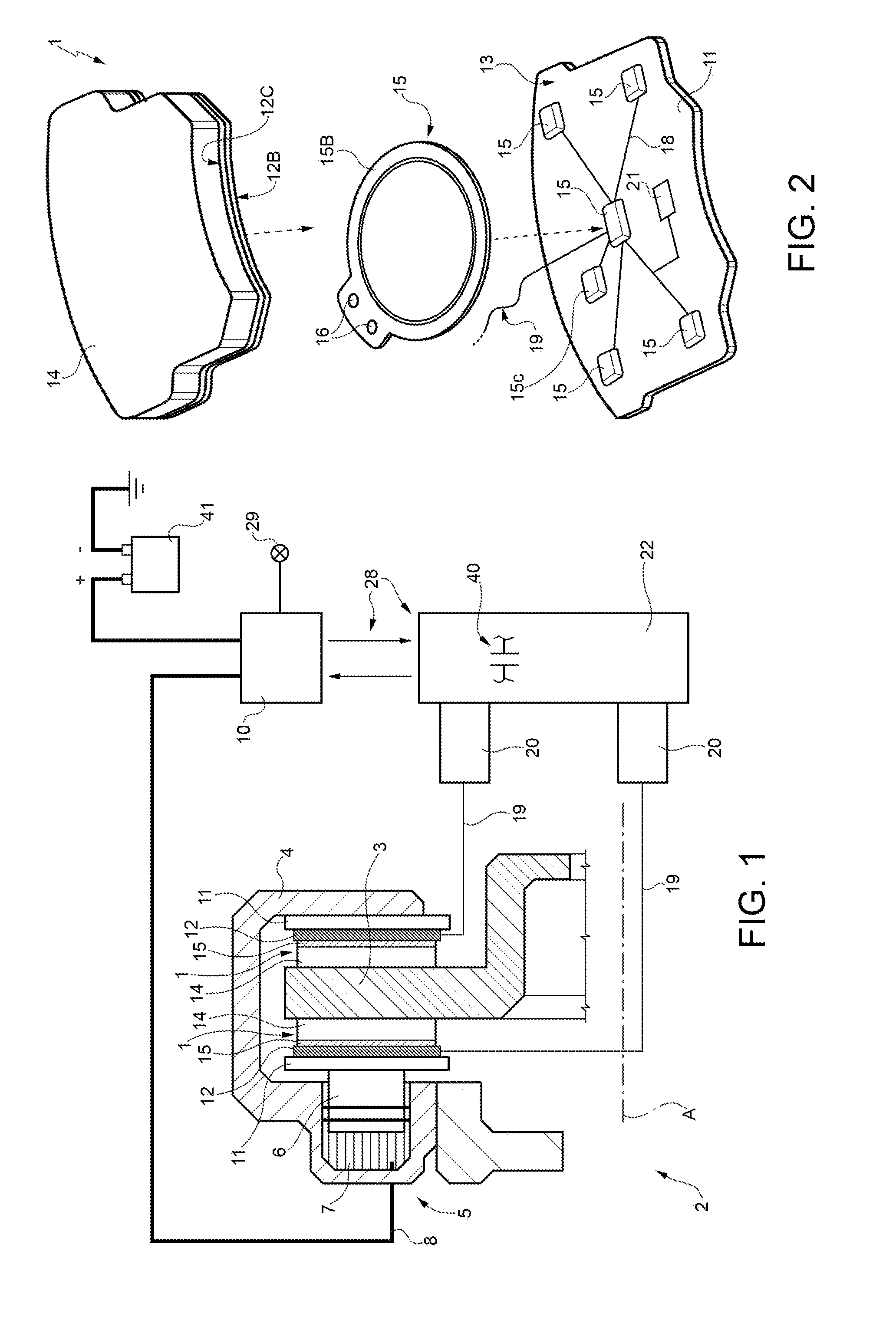
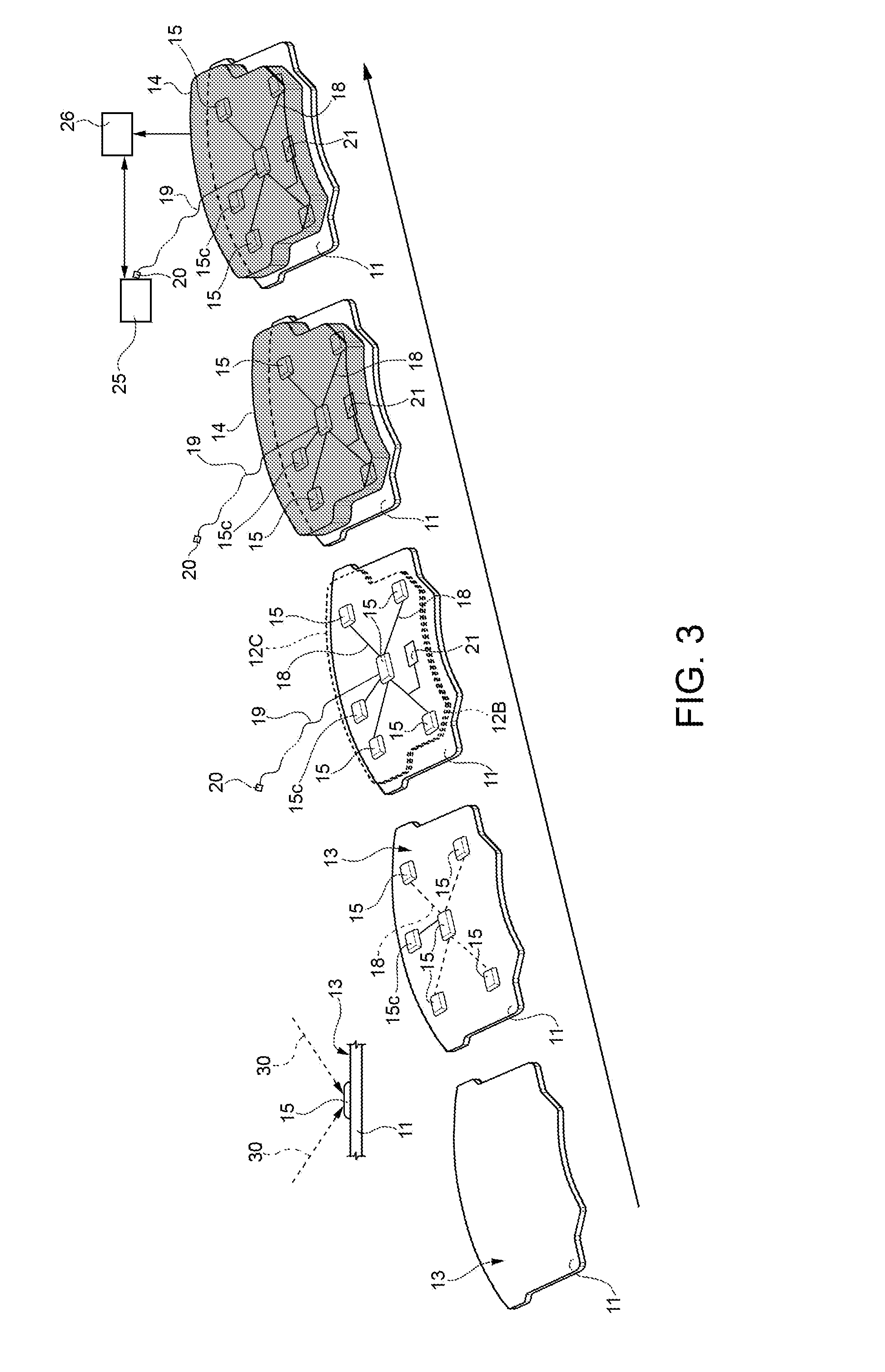
[0030]With reference to FIGS. 1 to 3 it is indicated as a whole at 1 a vehicle braking element integrated with sensors, in the shown example a brake pad, which is intended to equip a braking system 2 (FIG. 1), equipped with a disc 3 (disc-braking system); a disc 3 is attached in a known manner to each wheel of the vehicle (not shown for simplicity), and therefore rotates about a wheel axis A.

[0031]In addition to the disc 3 and for each disc 3 (therefore for each wheel of the vehicle) the braking system 2 comprises, a brake caliper 4 equipped with an actuator 5, known in the example illustrated to be of the oil-hydraulic type 5 but that can also be of an electrical type, and a pair of brake pads 1 carried by the brake caliper 4 together with the actuator 5, brake pads 1 which in use may be pressed against the disc 3 in a direction parallel to the axis A by means of the actuator 5, so as to brake the rotation of the disc 3, thus braking along with it the wheel to which it is rigidly a...


PUM

PropertyMeasurementUnit
temperaturesaaaaaaaaaa
Curie temperatureaaaaaaaaaa
operating temperaturesaaaaaaaaaa

Abstract

A method in which at least one piezoceramic sensor, which converts every mechanical force to which it is subjected into an electrical signal and having a Curie temperature higher than 200° C., is solidarized directly onto the surface of a metal support element of a vehicle braking element, which during use faces a vehicle element to be braked. While in contact with such a surface, an electrical circuit is implemented that picks up and eventually processes the electrical signal, the electrical circuit being connected with a connector integrated with the metal support element. An electrically insulating layer sandwiches the at least one piezoceramic sensor and the electrical circuit, and a block of friction material with an underlying damping layer is formed upon the electrically insulating layer. After forming the block of friction material, the piezoceramic sensor is polarized by applying a predetermined potential difference thereto by means of the connector.

Description

CROSS REFERENCE TO RELATED APPLICATION[0001]This application is a continuation of International Application No. PCT / IB2013 / 060881, filed Dec. 12, 2013, which claims priority under relevant sections of 35 U.S.C. §119 to Italian Patent Application No. TO2013A000307, filed Apr. 17, 2013. The entire contents of each above-noted application is herein incorporated by reference.TECHNICAL FIELD[0002]The present invention relates to a method for manufacturing braking elements, in particular brake pads with integrated sensors that allow to detect the forces acting upon brake pads during vehicle braking. The invention also relates to a brake pad integrated with sensors constructed using this method and to a vehicle braking system and associated control method both of which make use of a brake pad with integrated sensor as according to the invention.BACKGROUND OF THE INVENTION[0003]With the vehicle braking systems currently in production, there is no way to detect while using the vehicle, if no...

Claims


Application Information

Patent Timeline
Patent Type & Authority Applications(United States)
IPC IPC(8): B60T17/22F16D66/00F16D65/092
CPCB60T17/22F16D2066/005F16D66/00F16D65/092F16D65/08F16D2066/001F16D2069/006F16D65/0006F16D66/026F16D69/00Y10T29/42G01L1/16G01L5/28G01L5/225
Inventor MARTINOTTO, LUCAMERLO, FABRIZIODONZELLI, DANIELE
Owner ITT ITAL SRL
Why Eureka
Try Eureka