Local Coil

Active Publication Date: 2014-10-23
SIEMENS HEALTHCARE GMBH
View PDF3 Cites 7 Cited by
  • Summary
  • Abstract
  • Description
  • Claims
  • Application Information

AI Technical Summary

Benefits of technology

[0022]The local coil of the disclosed embodiments may replace a large detuning control current with a small detuning control current. With 10 mA and 100 mA as an example, the 100 mA detuning control current may instead simultaneously supply a detuning control current to as many as 10 local coils in some embodiments. Savings may thus be realized on the tuning/detuning control current and control modules of the system. The detuning control

Problems solved by technology

Furthermore, the number of diodes and inductors that may be connected in series in a diode

Method used


Image

  • Local Coil
  • Local Coil

Examples


Example

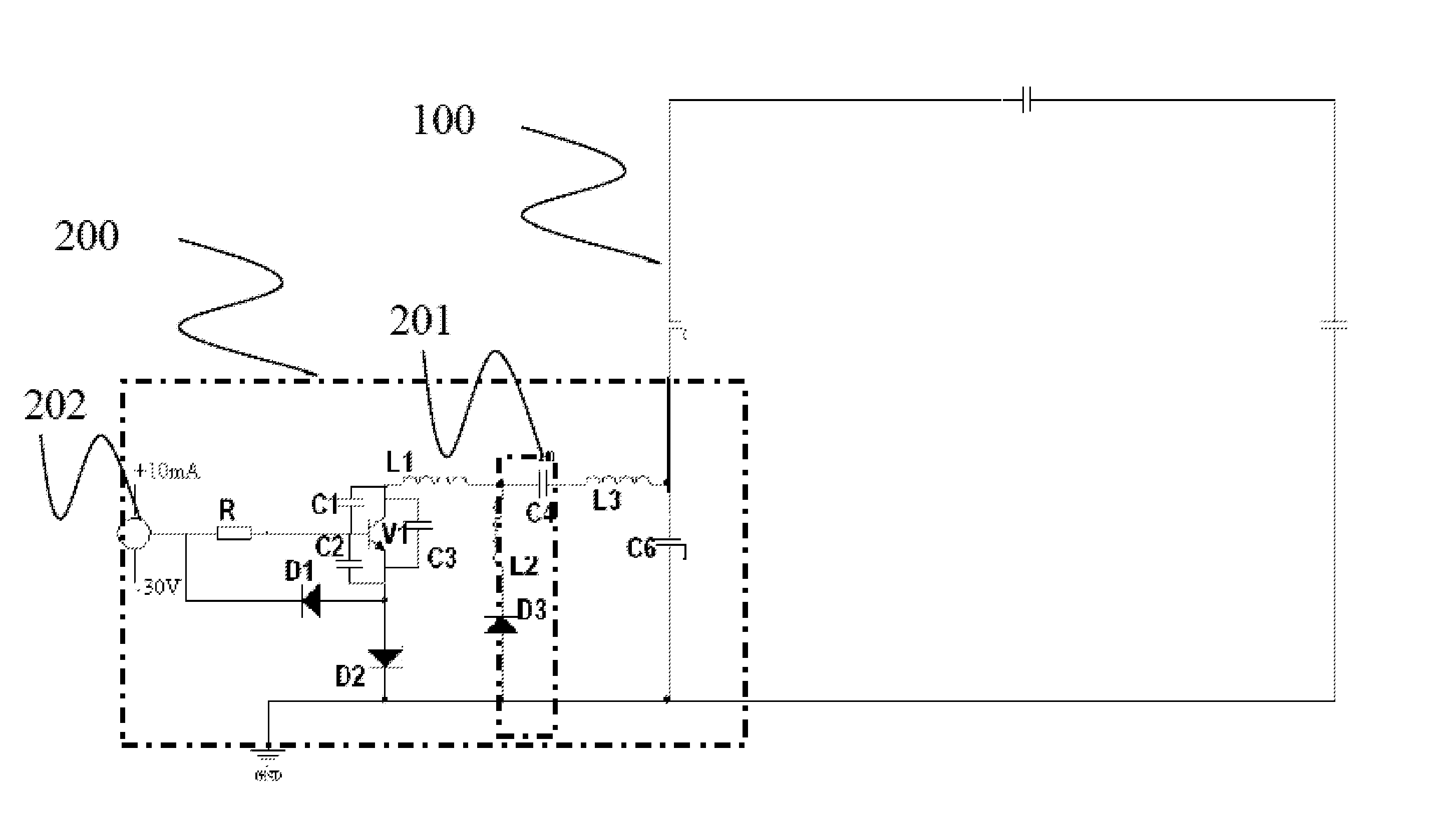
[0024]The disclosed embodiments provide a local coil for an MRI system. The local coil includes a signal antenna part to receive a magnetic resonance signal, and a tuning / detuning circuit part to subject the signal antenna part to switch control according to a control signal. The tuning / detuning circuit part is connected to the signal antenna part. The tuning / detuning circuit includes a control signal interface, a resonant circuit and an AC / DC conversion circuit. The control signal interface receives the control signal, the resonant circuit includes a diode, the AC / DC conversion circuit converts an alternating current generated by an electromagnetic wave to a direct current, and the AC / DC conversion circuit is connected in series with the diode. The diode is a PIN diode.

[0025]Electromagnetic waves are ubiquitous in the air. In some embodiments, the electromagnetic waves include RF pulses of the MRI system utilized by the local coil. Other electromagnetic wave sources may be used, su...


PUM


Abstract

A local coil for an MRI system includes a signal antenna to receive a magnetic resonance signal and a tuning/detuning circuit to subject the signal antenna part to switch control according to a control signal. The tuning/detuning circuit is connected to the signal antenna part. The tuning/detuning circuit includes a control signal interface, a resonant circuit and an AC/DC conversion circuit. The control signal interface receives the control signal. The resonant circuit includes a diode. The AC/DC conversion circuit converts an alternating current generated by an electromagnetic wave to a direct current. The AC/DC conversion circuit is connected in series with the diode. A small detuning control current may be used, and detuning control circuitry may be reduced.

Description

[0001]This application claims the benefit of CN 201310125226.X, filed on Apr. 11, 2013, which is hereby incorporated by reference in its entirety.BACKGROUND[0002]The disclosed embodiments relate to magnetic resonance imaging systems, and to a local coil for a magnetic resonance imaging system.[0003]Magnetic resonance imaging (MRI) is a technology in which the phenomenon of magnetic resonance is utilized for the purpose of imaging. The main principles of magnetic resonance are as follows. Where an atomic nucleus contains a single proton (e.g., the nuclei of the hydrogen atoms present throughout the human body), the proton exhibits spin motion and resembles a small magnet. Moreover, the spin axes of these small magnets lack a definite pattern. If an external magnetic field is applied, the small magnets are rearranged according to the magnetic force lines of the external field. The magnets line up in one of two directions, either parallel or anti-parallel to the magnetic force lines of...

Claims


Application Information

Patent Timeline
IPC IPC(8): G01R33/36G01R33/34
CPCG01R33/34G01R33/3628G01R33/341G01R33/3657
Inventor TAN, JIA HENGTONG, TONGVESTER, MARKUSWANG, JIANMIN
Owner SIEMENS HEALTHCARE GMBH
Why Eureka
Try Eureka