
Nonlinear inductor

a technology of inductance and inductance, applied in the field of inductance, can solve the problems of harmonic distortion, power factor, unnecessary electromagnetic interference, etc., and achieve the effect of saving the cost of air gap

Inactive Publication Date: 2014-10-23
DELTA ELECTRONICS INC
View PDF8 Cites 15 Cited by
  • Summary
  • Abstract
  • Description
  • Claims
  • Application Information

AI Technical Summary

Benefits of technology

The present invention provides a nonlinear inductor with multiple ways to adjust the inductance without extra mold opening, which allows for high inductance at low current operation and low inductance at high current operation. The inductor includes a first magnetic core, a second magnetic core, a third magnetic core, a fourth magnetic core, a fifth magnetic core, and a coil unit. The magnetic cores are arranged in a specific pattern to create air gaps with different widths, which results in different magnetic resistances and thus the adjustment of the inductance. The invention also provides an enhanced design that allows for easy adjustment of the inductance by adding or removing elements without requiring major modifications to the inductor.

Problems solved by technology

In an electrical system driven by a variable-frequency drive (VFD), there are signals switching in high frequency existing in the circuitry of the VFD and the motor, which may result in unnecessary electromagnetic interference, so as to reduce the power factor of the VFD and generate a harmonic distortion on the output loading.
The total harmonic distortion is even higher when the VFD is at low current operation.
If the harmonic distortion is too high, the performance of the system may be reduced, and the devices in the system may even be damaged.
But if the inductance is too high, the voltage drops in the output terminals of the VFD at the high current operation.
The shape variation of the air gaps, which is build with the extra mold opening, is often applied to implement the nonlinear inductor; however, such shape variation need additional molds in fabrication and thus extra cost.

Method used


Image

  • Nonlinear inductor
  • Nonlinear inductor
  • Nonlinear inductor

Examples


Embodiment Construction

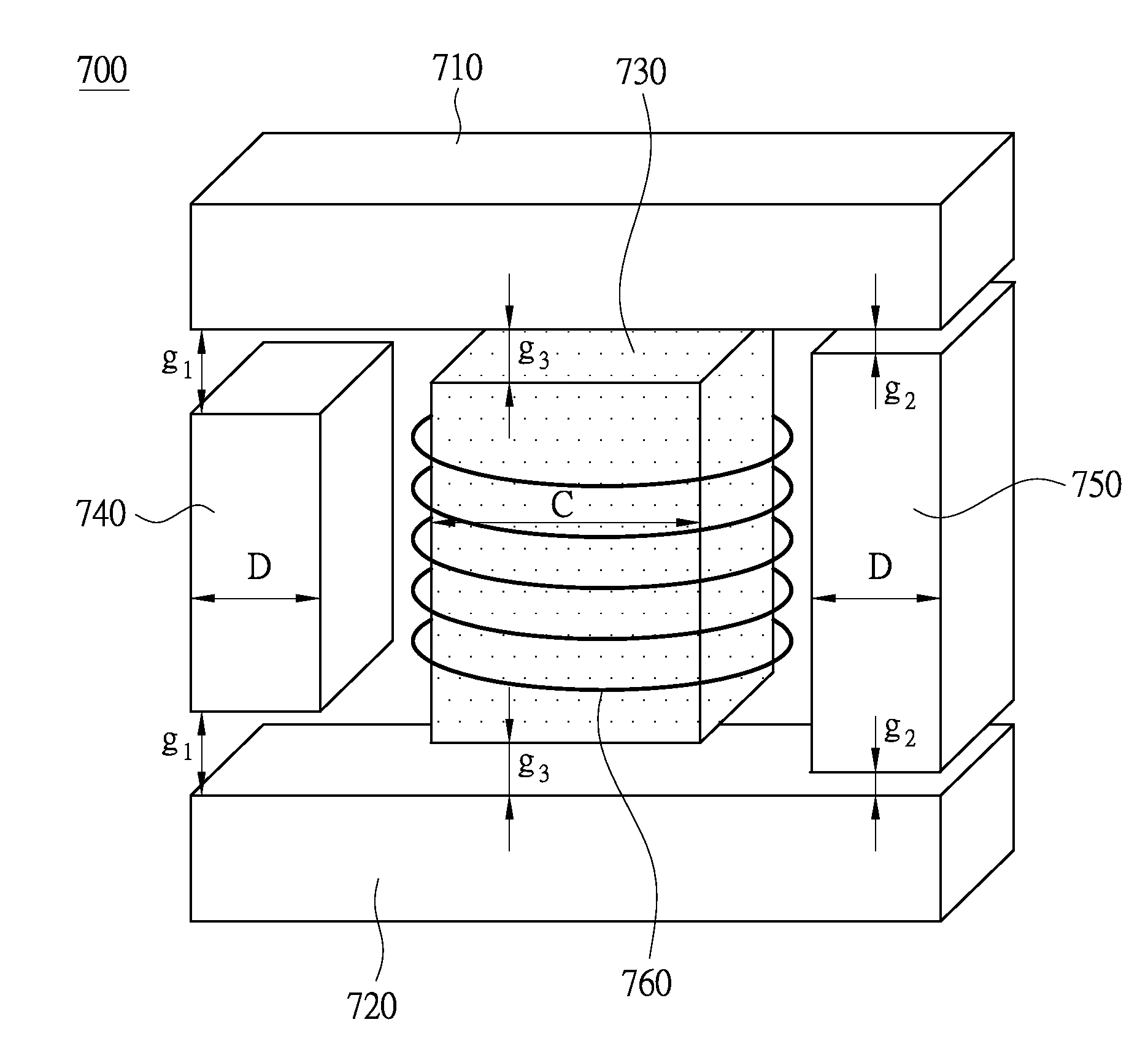
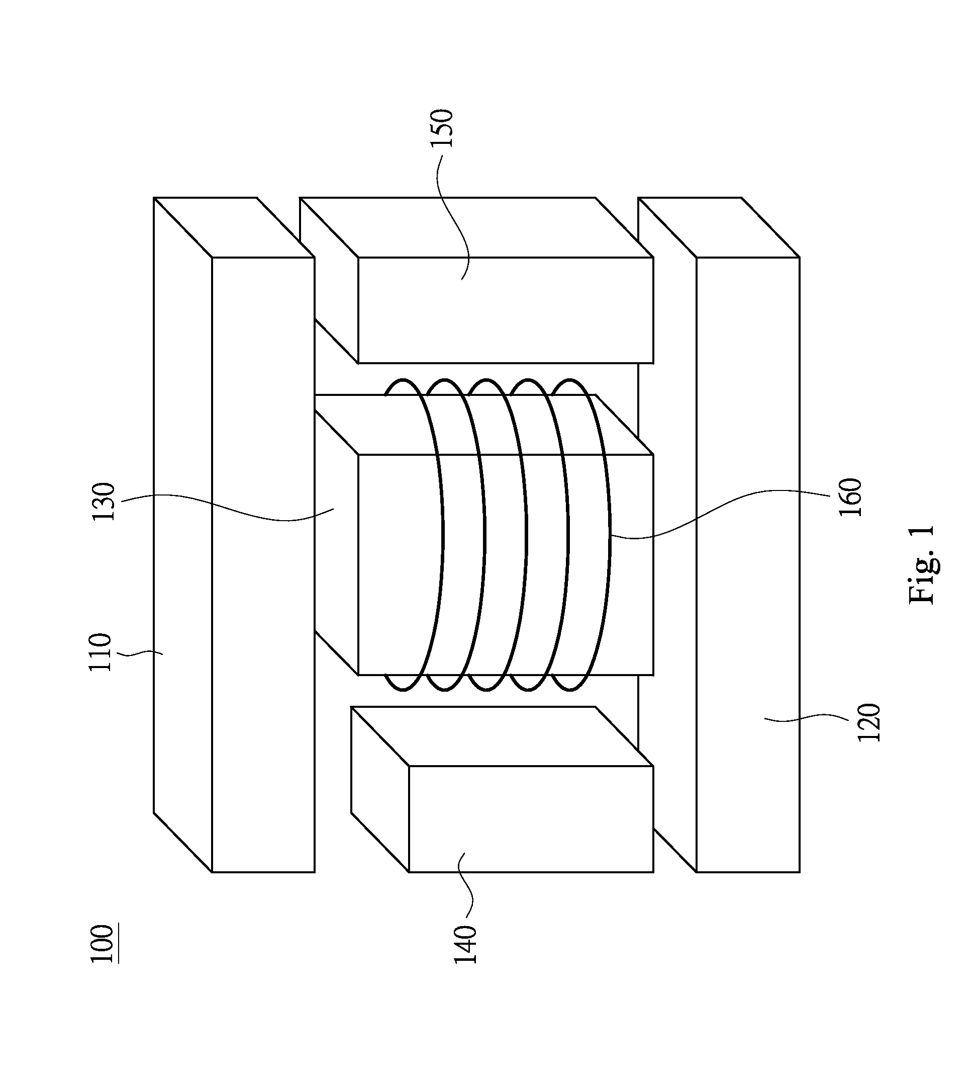
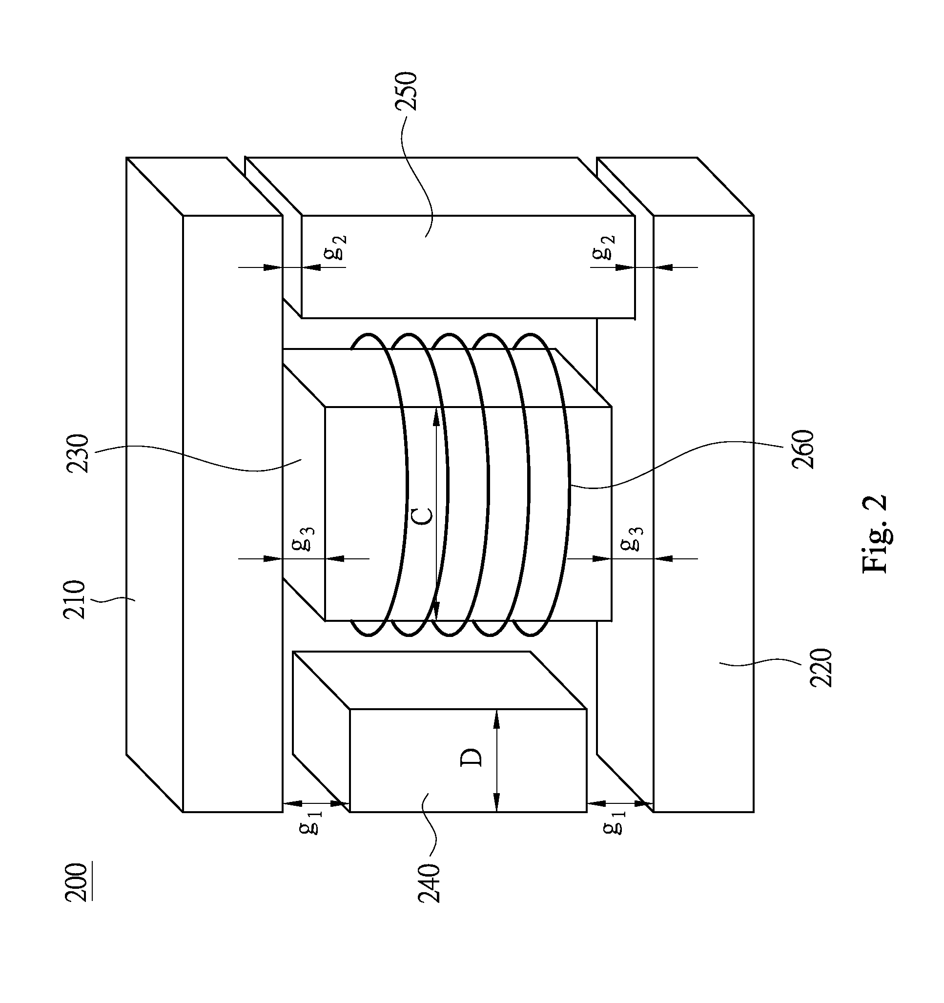
[0031]Reference will now be made in detail to the present embodiments of the invention, examples of which are illustrated in the accompanying drawings. Wherever possible, the same reference numbers are used in the drawings and the description to refer to the same or like parts.

[0032]As used herein, “around”, “about” or “approximately” shall generally mean within 20 percent, preferably within 10 percent, and more preferably within 5 percent of a given value or range. Numerical quantities given herein are approximate, meaning that the term “around”, “about” or “approximately” can be inferred if not expressly stated.

[0033]It will be understood that, although the terms first, second, third etc. may be used herein to describe various elements, components, regions, layers and / or sections, these elements, components, regions, layers and / or sections should not be limited by these terms. These terms are only used to distinguish one element, component, region, layer or section from another el...


PUM

PropertyMeasurementUnit
widthaaaaaaaaaa
widthaaaaaaaaaa
widthaaaaaaaaaa

Abstract

A non-linear inductor is disclosed herein. The non-linear inductor includes a first magnetic core, a second magnetic core, a third magnetic core, a fourth magnetic core, a fifth magnetic core and a coil unit. The first and the second magnetic core are disposed in parallel. The third magnetic core, the fourth magnetic core and the fifth magnetic core are all vertically disposed between the first and the second magnetic core. The fourth magnetic core is vertically disposed between the first and the second magnetic core. The fourth and the fifth magnetic core are disposed at both sides of the third magnetic core in parallel. The coil unit winds around the third magnetic core. A magnetic resistance of the fourth magnetic core passed through by an inductive magnetic flux is different from a magnetic resistance of the fifth magnetic core passed through by the inductive magnetic flux.

Description

RELATED APPLICATIONS[0001]This application claims priority to Taiwan Application Serial Number 102114018, filed Apr. 19, 2013, which is herein incorporated by reference.BACKGROUND[0002]1. Field of Invention[0003]The present invention relates to an inductor. More particularly, the present invention relates to a nonlinear inductor with a set of the asymmetrical magnetic resistance.[0004]2. Description of Related Art[0005]In an electrical system driven by a variable-frequency drive (VFD), there are signals switching in high frequency existing in the circuitry of the VFD and the motor, which may result in unnecessary electromagnetic interference, so as to reduce the power factor of the VFD and generate a harmonic distortion on the output loading.[0006]The total harmonic distortion is even higher when the VFD is at low current operation. If the harmonic distortion is too high, the performance of the system may be reduced, and the devices in the system may even be damaged. To reduce the h...

Claims


Application Information

Patent Timeline
Patent Type & Authority Applications(United States)
IPC IPC(8): H01F27/24
CPCH01F27/24H01F3/14H01F27/385H01F38/023
Inventor KUO, TSUNG-NANLI, MING-XIAN
Owner DELTA ELECTRONICS INC
Learn More