
System and method for nonlinear radar

a nonlinear radar and system technology, applied in the field of systems and methods for nonlinear radar, can solve the problems of not working for a general radar, not being widely applied to problems with uncontrolled targets, and not being able to discriminate between active and passive targets (domain 7) highly developed

Inactive Publication Date: 2014-10-23
APPLIED SIGNALS INTELLIGENCE
View PDF1 Cites 68 Cited by
  • Summary
  • Abstract
  • Description
  • Claims
  • Application Information

AI Technical Summary

Benefits of technology

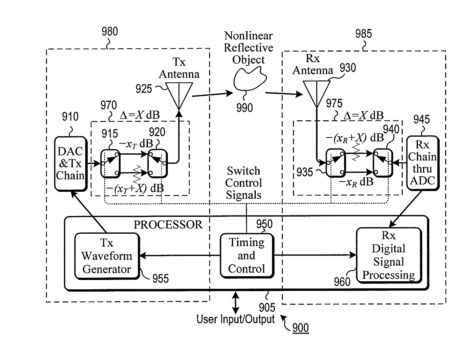
The patent describes a nonlinear radar system that generates power-modified transmission pulses and receives power-modified reflected pulses to detect and locate objects. The system includes a transmitter circuit, a switchable transmitter power-modifying circuit, a transmitter antenna, a receiver antenna, a receiver circuit, and a timing control circuit. The technical effects of the patent include improved detection and location of remote objects, improved power-modulation accuracy, and improved transmission and reception of power-modified pulses.

Problems solved by technology

The problem with the approach shown is that while it works for a highly control test apparatus, it does not work for a general radar problem where the backscatter signal picked up by the receiver is a high dynamic range random process due to the transmit signals interaction with random targets and clutter.
The problem is that even as highly developed as radar has become in the domains of (1) to (6) listed in the previous paragraph, its ability to discriminate between active and passive targets (domain (7)) is not highly developed.
Furthermore, the use of NLR to remotely collect information-bearing modulation on the nonlinear backscatter signal and use it to aid discrimination, classification, determination of circuit conditions, and to remotely receive data when the circuit conditions are modulated by data has not been done heretofore.
While NLR has been used in specialty applications like tracking insects tagged with a tiny diode and wideband antenna, it has not been broadly applied to problems that have uncontrolled targets-of-opportunity.
LEDs are difficult to detect simply because they are surrounded by so much clutter.
They are currently causing significant damage to US and allied forces.
A small but hard set of problems has caused previous NLR systems to fail to obtain the wide use that linear radar has enjoyed.
From a phenomenology perspective, the key problems with even an ideal NLR are (1) that the received signal, in free space, power falls off in range (R) as a function of R8 (for the 3rd order term) as opposed to normal radar that falls off with R4, and (2) that the nonlinear radar cross section (NL-RCS) is much smaller than the normal body-size driven RCS.
Together, these two factors drastically reduce the operational range of even an ideal, perfectly linear, radar.
As such, this 24 dB of integration would not work and would only reveal the radar's own nonlinearites.
The difficulty of reducing nonlinear terms is particularly difficult for the receiver.
An IED is only hard to detect because it is surrounded by so much similar looking clutter.
If successful, such a radar would dramatically affect operations where LEDs are a threat.
But that leaves problems (a)-(d).
These problems are significant since the dynamic range required is beyond that achievable directly with standard wideband hardware.
Even though narrowband architectures might provide the needed dynamic range by virtue of ultra-linear passive narrow bandwidth filters (such as LC, SAW, crystal, etc.), they fail at addressing (c) because their narrow bandwidth prevents them from providing the required radar range resolution.
Even though ultra high linearity push-pull Class-A or Class AB amplifiers might be operated to give the needed low harmonic and spurious emissions, they fail to address (d) due to their extremely low efficiency at operating points that provide the required linearity.
What the model cannot capture is the affect of coupling.
They do not work well, however, in a domain where nonlinear terms need to be over 90 dB down from the fundamentals, as is the case with NLR.

Method used


Image

  • System and method for nonlinear radar
  • System and method for nonlinear radar
  • System and method for nonlinear radar

Examples


Embodiment Construction

[0087]The instant disclosure is provided to further explain in an enabling fashion the best modes of performing one or more embodiments of the present invention. The disclosure is further offered to enhance an understanding and appreciation for the inventive principles and advantages thereof, rather than to limit in any manner the invention. The invention is defined solely by the appended claims including any amendments made during the pendency of this application and all equivalents of those claims as issued.

[0088]It is further understood that the use of relational terms such as first and second, and the like, if any, are used solely to distinguish one from another entity, item, or action without necessarily requiring or implying any actual such relationship or order between such entities, items or actions. It is noted that some embodiments may include a plurality of processes or steps, which can be performed in any order, unless expressly and necessarily limited to a particular or...


PUM


Abstract

A non-linear radar is disclosed that is able to detect non-linear target responses that are below the harmonic-noise floor of the radar. To accomplish this below-the-noise-floor sensitivity feature the proposal specifically addresses all of the problems commonly faced by non-linear radar such as linearity of the transmitter path, receiver path, and size, weight, and power, and cost (SWaP-C). The radar operates in both standard and nonlinear modes with signal processing that allows display of nonlinear alone, linear alone, or both types of backscatter. Different combinations of six methodologies allow customization to fit different application needs, from low-cost modest performance, to higher cost and extremely high performance.

Description

CROSS-REFERENCE TO RELATED APPLICATIONS[0001]This application claims priority from provisional application 61 / 812,995, filed on 17 Apr. 2013, titled “SYSTEM AND METHOD FOR NONLINEAR RADAR,” the contents of which are incorporated by reference in their entirety.FIELD OF THE INVENTION[0002]This application relates to a system and method for generating and sending signals and receiving linear and nonlinear reflections of those signals. Furthermore, objects reflecting those signals can reflect not only the sent signals and harmonics of the sent signals, but also add their own modulation to those reflected signals. More particularly it relates to a system and method for realizing a nonlinear radar (NLR) that not only detects the presence of linear and nonlinear terms, but also detects modulation on those terms. More particularly it relates to a system and method for generating, sending and receiving signals for the purpose of detecting, ranging, and discriminating between different object...

Claims


Application Information

Patent Timeline
Patent Type & Authority Applications(United States)
IPC IPC(8): G01S7/28G01S13/02
CPCG01S13/02G01S7/28G01S7/41G01S13/106G01S13/28G01S13/887
Inventor MCCORKLE, JOHN W.
Owner APPLIED SIGNALS INTELLIGENCE
Learn More