Positioning anatomical landmarks in volume data sets

anatomical landmarks and volume data sets are applied in the field of three-dimensional (3d) image data sets, which can solve the problems of inherently dynamic and noisy, incorrect configuration of detected landmarks, and incorrect identification of landmarks, so as to avoid the error of correcting the placement of other landmarks

Active Publication Date: 2014-10-23
TOSHIBA MEDICAL SYST CORP
View PDF4 Cites 13 Cited by
  • Summary
  • Abstract
  • Description
  • Claims
  • Application Information

AI Technical Summary

Problems solved by technology

However, the nature of patient data is that it is inherently dynamic and noisy.
Moreover, the human body comes in a wide variety of shapes and forms, for example as dictated by age, so accurate positioning of landmarks in a patient image will always be a challenge.
A discriminative classification approach to place anatomical landmarks will generate possible candidate locations independently of each other which can be a disadvantage as now described with an example.
However, according to anatomical knowledge, the correct configuration of the detected landmarks is violated.
This is due to the absence of global awareness to the relative location of landmarks.
Correctly identified landmarks are not able to assist in correcting errors in the placement of other landmarks.
In particular, the modelled (dot) landmark inside the oval in the right hand side of the figure is grossly misplaced compared to the ground truth (cross) landmark which is some distance above it, but the classification forest model is not able to use the (almost) correctly placed neighbouring landmarks as a cue to correct the grossly misplaced landmark.
The placement of head landmarks by the classification forest takes place, because the decision forest is not spatially aware of neighbouring detected landmarks, so their position will not be corrected despite the obvious misclassification error.

Method used


Image

  • Positioning anatomical landmarks in volume data sets
  • Positioning anatomical landmarks in volume data sets
  • Positioning anatomical landmarks in volume data sets

Examples


examples

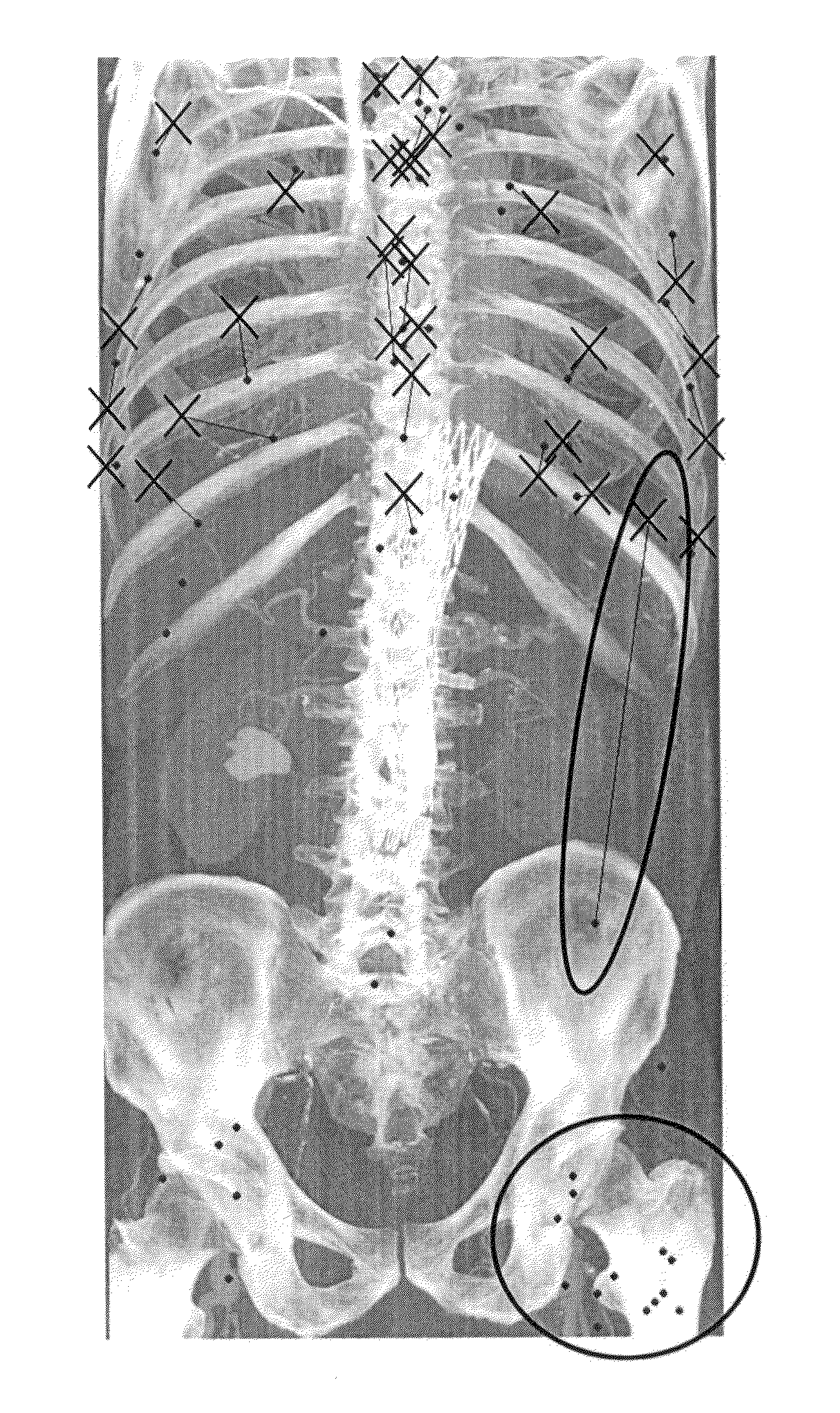
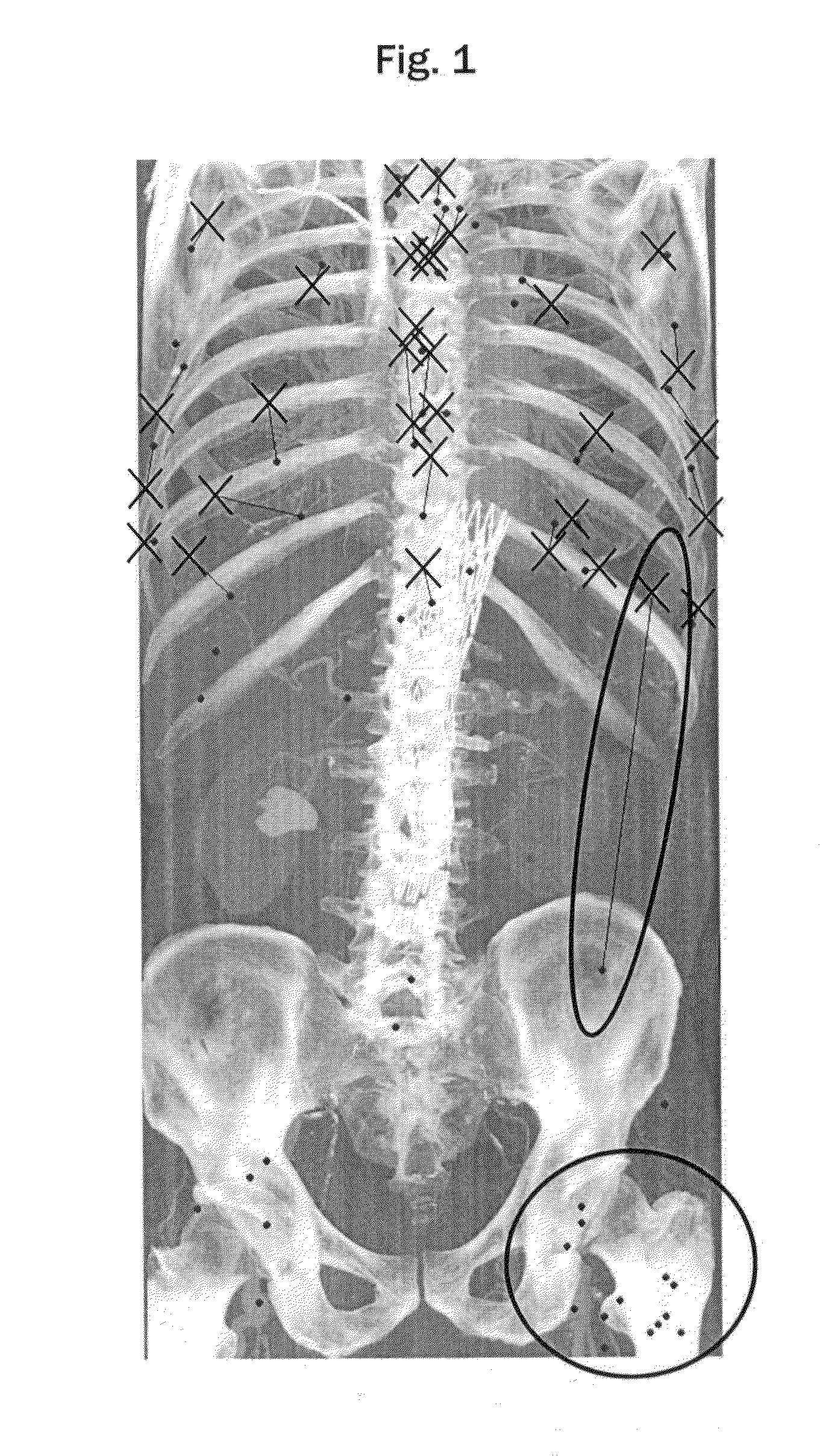
[0147]FIG. 12 shows a CT image of the human body. The cross points are ground truth landmarks. The dot points are the landmarks as positioned by the above described method of using a decision forest to initially place the landmarks followed by using a PDM to adjust the landmark positions. The lines interconnect corresponding landmarks and thus show the error from ground truth of the automatically placed landmarks.

[0148]As well as correcting the detection rates and locations of landmarks placed by the decision forest, the PDM also infers unmarked landmarks (as shown in the head).

[0149]FIGS. 13 to 18 show a number of pairs of CT images labelled A and B, where the ‘A’ label images show the intermediate result after the initial landmark placement by the decision forest, but before optimisation using the PDM, and the ‘B’ label images show the final result after the PDM has been applied. As in previous figures, the cross points are ground truth landmarks, the dot points are the automatica...


PUM


Abstract

Certain embodiments provide a computer apparatus operable to carry out a data processing method to position a set of anatomical landmarks in a three-dimensional image data set of a part or all of a patient, comprising: providing a trained supervised machine learning algorithm which has been trained to place each of the set of anatomical landmarks; applying the supervised machine learning algorithm to place the set of anatomical landmarks relative to the data set; providing a trained point distribution model, including a mean shape and a covariance matrix, wherein the mean shape represents locations of the set of landmarks in a variety of patients; and applying the point distribution model to the set of landmarks with the locations output from the supervised machine learning algorithm by: removing any landmarks whose locations have an uncertainty above a threshold with reference to the mean shape and covariance matrix; followed by: an optimisation of the locations of the remaining landmarks by maximising joint likelihood that a new shape, derived from linear combinations of eigenvectors of the covariance matrix, is plausible.

Description

BACKGROUND OF THE INVENTION[0001]Embodiments described herein generally relate to three-dimensional (3D) image data sets of a patient and in particular how to position anatomical landmarks therein.[0002]In the medical field, three-dimensional (3D) image data sets, i.e. volume data sets, are collected by a variety of techniques—referred to as modalities in the field—including computer assisted tomography (CT), magnetic resonance (MR), single photon emission computed tomography (SPECT), ultrasound and positron emission tomography (PET). Volume data comprises a plurality of voxels arranged in a 3D grid. Each voxel has a voxel value associated with it. The voxel values represent measurements of a physical parameter. For example, in the case of CT scans, the voxel values represent the opacity of those voxels to X-rays, i.e. their X-ray stopping power. X-ray stopping power is measured in Hounsfield units (HUs) which is closely correlated with density (mass per unit volume).[0003]Anatomica...

Claims


Application Information

Patent Timeline
Patent Type & Authority Applications(United States)
IPC IPC(8): G06T7/00G06K9/00G06V10/764
CPCG06K9/00201G06T7/0012G06T2207/10081G06T2207/20081G06T2207/30008G06T7/73G06V10/764G06F18/24323
Inventor DABBAH, MOHAMMADPOOLE, IAN
Owner TOSHIBA MEDICAL SYST CORP
Why Eureka
Try Eureka