
Bone prosthesis for maintaining joint operation in complex joints

a bone prosthesis and complex joint technology, applied in the field of joint repair and replacement, can solve the problems of degenerative arthritis, increased pressure and wear on the dorsal aspect of the scaphoid fossa, and abnormal wear and degeneration of the radial styloid

Active Publication Date: 2014-10-23
ROGACHEFSKY RICHARD A
View PDF0 Cites 5 Cited by
  • Summary
  • Abstract
  • Description
  • Claims
  • Application Information

AI Technical Summary

Benefits of technology

The patent is about a better way to replace parts of the wrist, specifically the scaphoid. The method involves removing the scaphoid and replacing it with a scaphoid implant that has a magnetic element. A magnetic relationship exists between the implant and the adjacent bones. This allows for a more secure and accurate replacement of the scaphoid. The prosthesis also includes magnetic bone implants that have a magnetic relationship with the scaphoid and adjacent bones. In cases where more joint surfaces are affected by the disease process, more magnetic connections may be needed. Overall, the invention provides an improved solution for replacing damaged wrist components.

Problems solved by technology

Due to the fact that the scaphoid is volar flexed it has difficulty clearing the radial styloid with wrist flexion and extension, causing abnormal wear and degeneration at the radial styloid.
As a result of the scaphoid being in a more flexed position, increased pressure and wear occur on the dorsal aspect of the scaphoid fossa articular surface of the distal radius and dorsal aspect of the scaphoid.
With continued abnormal forces and wear, formation of degenerative arthritis occurs.
These types of drastic procedure can severely limit motion of the wrist after surgery.

Method used


Image

  • Bone prosthesis for maintaining joint operation in complex joints
  • Bone prosthesis for maintaining joint operation in complex joints
  • Bone prosthesis for maintaining joint operation in complex joints

Examples


Embodiment Construction

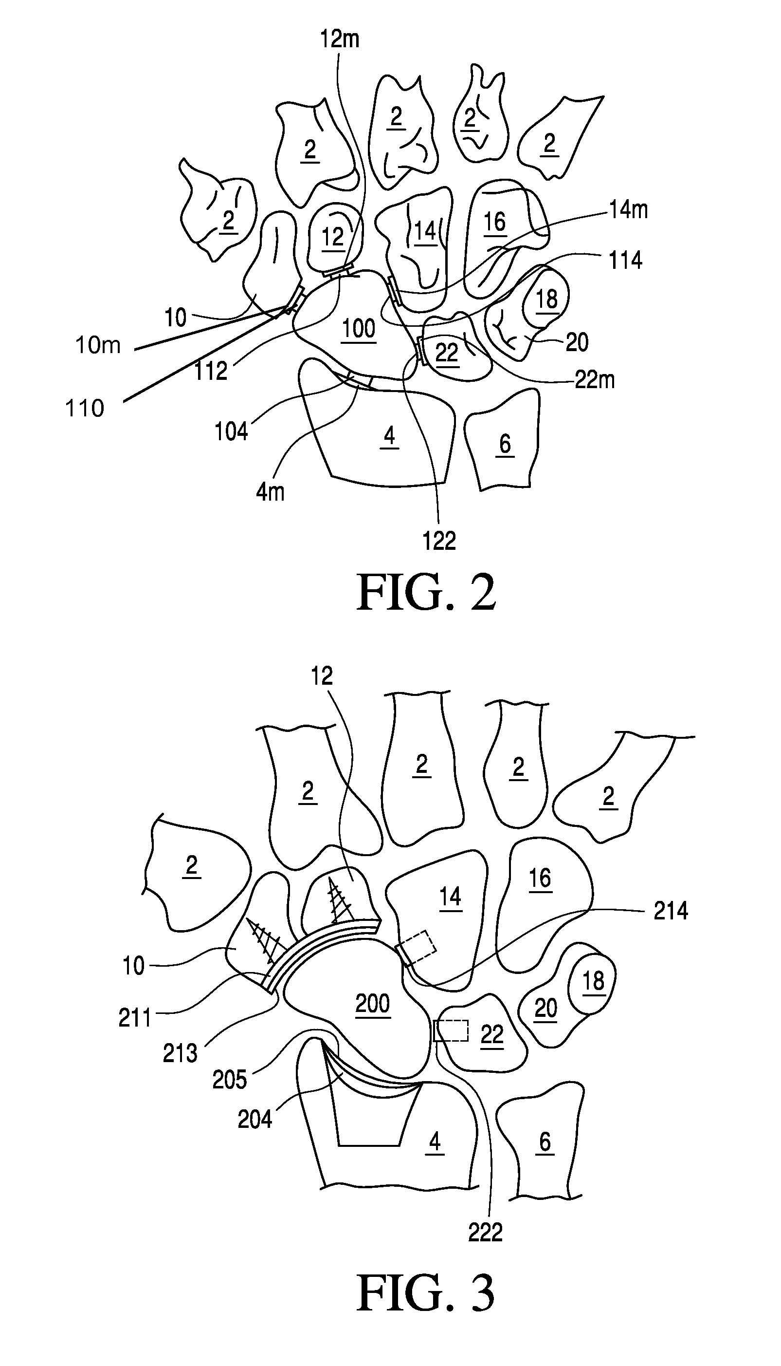
[0024]As noted above, the present invention relates to joint replacement. One present embodiment of the invention will be described with reference to FIG. 2.

[0025]As used herein, a “magnetic element” generally refers to a component that includes a magnet or that responds to a magnetic field, i.e., by being attracted to or repelled by a magnet.

[0026]A “magnetic implant” is a type of magnetic element that is implanted into the body.

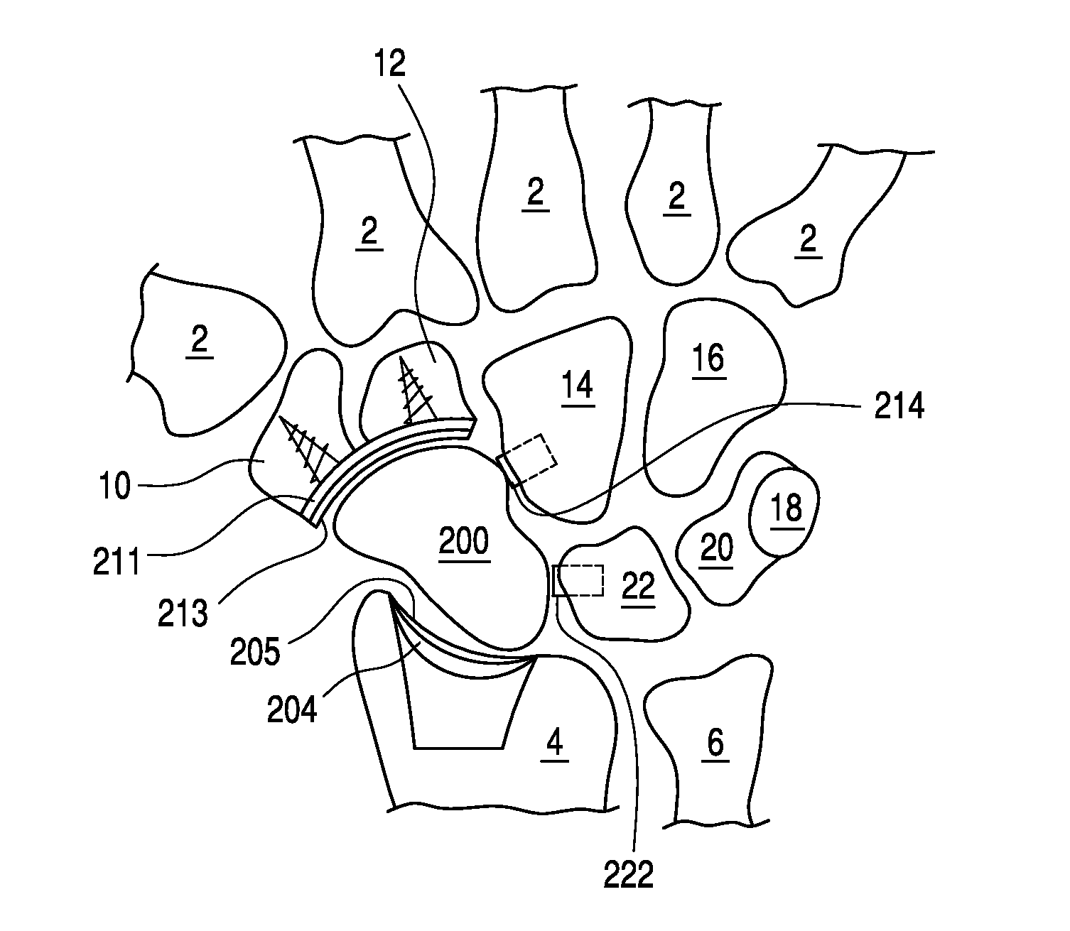
[0027]In FIG. 2, the bones of the wrist are illustrated. Specifically, the metacarpal bones 2, the radius 4 and seven of the carpal bones 10, 12, 14, 16, 18, 20, 22 are illustrated. Different from the natural anatomy of the hand, however, the scaphoid has been removed from the hand illustrated in FIG. 2. In its place, a magnetic implant, here a scaphoid implant 100 has been inserted such that the implant 100 is aligned proximate to the adjacent bones. The implant 100 is illustrated as having a generally oblong shape, substantially similar to the shape of th...


PUM


Abstract

A prosthesis for reconstructing a multibone joint such as a wrist. A patient's scaphoid is removed to create a void. The scaphoid has a plurality of adjacent bones, each of the adjacent bones comprising a surface generally facing the void. The surface of at least two of the adjacent bones is prepared by affixing a magnetic element thereto and a magnetic scaphoid implant is inserted into the void. A magnetic relationship exists between the magnetic elements and the magnetic scaphoid implant.

Description

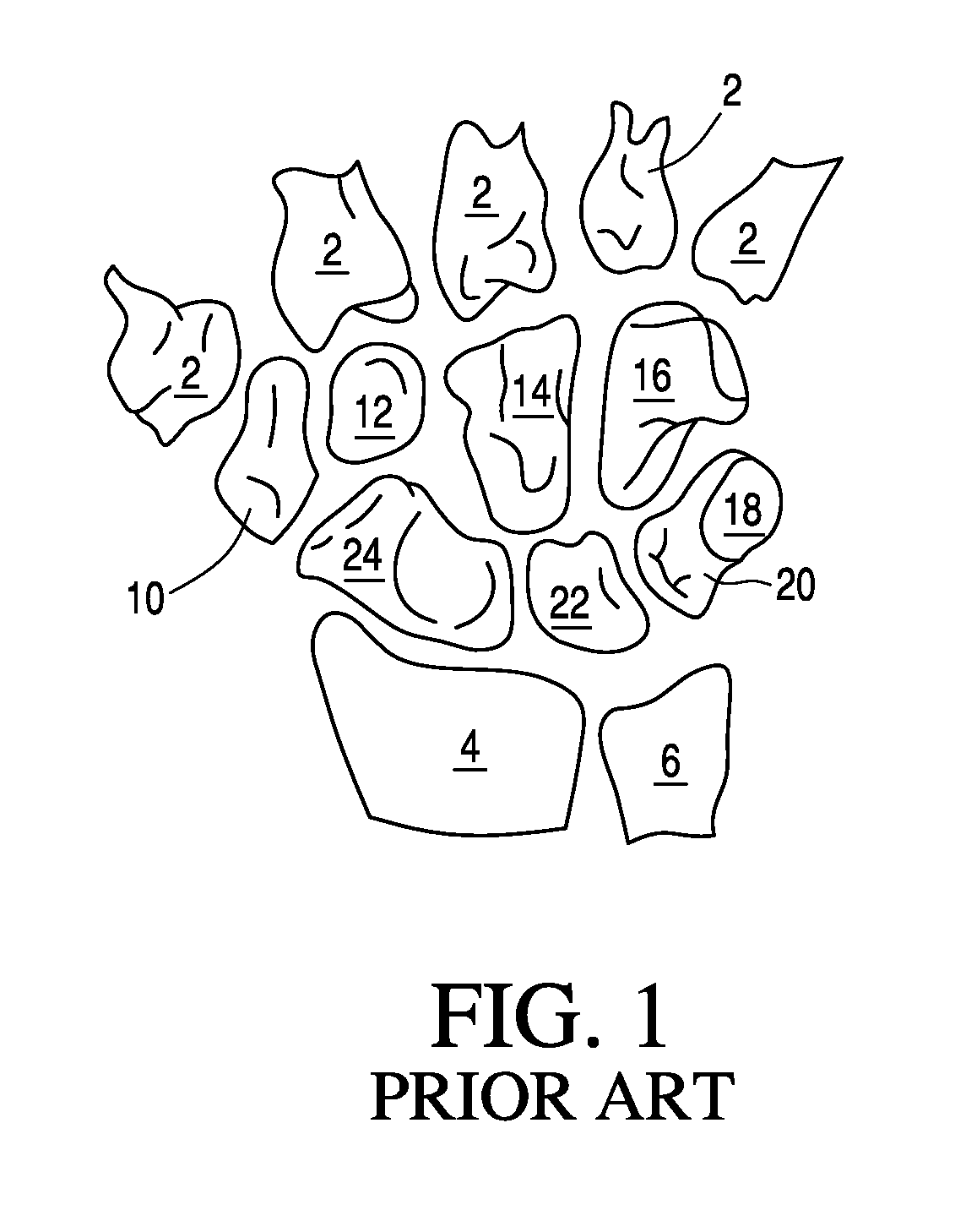
CROSS-REFERENCE TO RELATED APPLICATIONS[0001]This application is a divisional of prior filed, pending U.S. patent application Ser. No. 13 / 731,160 filed Dec. 31, 2012, the disclosure of which is incorporated by reference herein.FIELD OF THE INVENTION[0002]This invention relates generally to joint repairs and replacements. More specifically, this invention relates to repairing a wrist by replacing a bone proximate the joint with a prosthetic including a magnet.BACKGROUND OF THE INVENTION[0003]As is conventionally known, the wrist is a very intricate interconnection of several bones, ligaments and tendons. The cooperation of these results in an elegant system allowing for varied and complex movement. FIG. 1 shows the conventional structure, which includes five metacarpals 2, the radius 4, the ulna 6, and eight carpal bones. The carpal bones include the trapezium 10, the trapezoid 12, the capitate 14, the hamate 16, the pisiform 18, the triquetrum 20, the lunate 22, and the scaphoid 24....

Claims


Application Information

Patent Timeline
Patent Type & Authority Applications(United States)
IPC IPC(8): A61F2/42
CPCA61F2/4261A61F2002/30079A61F2002/4289A61F2002/4207A61F2002/4264A61F2002/4276A61F2002/4279A61F2/4202A61F2210/009A61F2/30721A61F2002/4212A61F2/42A61F2/4606A61F2002/4205A61F2002/421A61F2002/4266A61F2002/4287A61F2/30749A61F2002/30754A61F2002/4217A61F2002/4292
Inventor ROGACHEFSKY, RICHARD A.
Owner ROGACHEFSKY RICHARD A
Learn More