
Bottling line and method

Active Publication Date: 2014-10-30
SACMI COOP MECCANICI IMOLA S C R L
View PDF10 Cites 14 Cited by
  • Summary
  • Abstract
  • Description
  • Claims
  • Application Information

AI Technical Summary

Benefits of technology

The invention is a continuous cycle line and method for bottling containers of thermoplastic material that are reliable and efficient, while also ensuring high levels of hygiene. This results in a reduced overall size of the warehouse, as compared to the number of drawers, which helps to maximize the space available for product storage.

Problems solved by technology

Generally speaking, in the prior art solutions, the drawback relating to efficiency and reliability is tackled by installing accumulation systems between one unit and another, so as to avoid the need for connecting the units to each other by positive control of the objects transferred from one unit to another (indeed, in that case, the units are always in step with each other).
These accumulation systems, however, are to the disadvantage of line hygiene.
This solution, however, does not solve the problem of hygiene which is, in fact, made worse by the risk of the parisons getting dirty as they pass through the storage system.
However, patent IT1359024, too, fails to deal with the problem of hygiene and does not provide solutions able to guarantee the reliability and efficiency of the line.
Moreover, it should be noted that even document WO2009127962 does not provide solutions able to guarantee the reliability and efficiency of an entire bottling line but proposes only a solution to the problem of the reliability (that is, of the uninterrupted service) of the subsystem consisting of the blow-moulder and the parison moulding machine.
In light of this, it should be noted that the following problems exist in connection with the efficiency of the line.
The first consequence is that stopping the units too frequently can lead to problems.
In light of this, the solutions adopted by the prior art for bottling lines tend to limit the efficiency of the line on account of the need to strike a compromise between the above mentioned opposite needs.

Method used


Image

  • Bottling line and method
  • Bottling line and method
  • Bottling line and method

Examples


Embodiment Construction

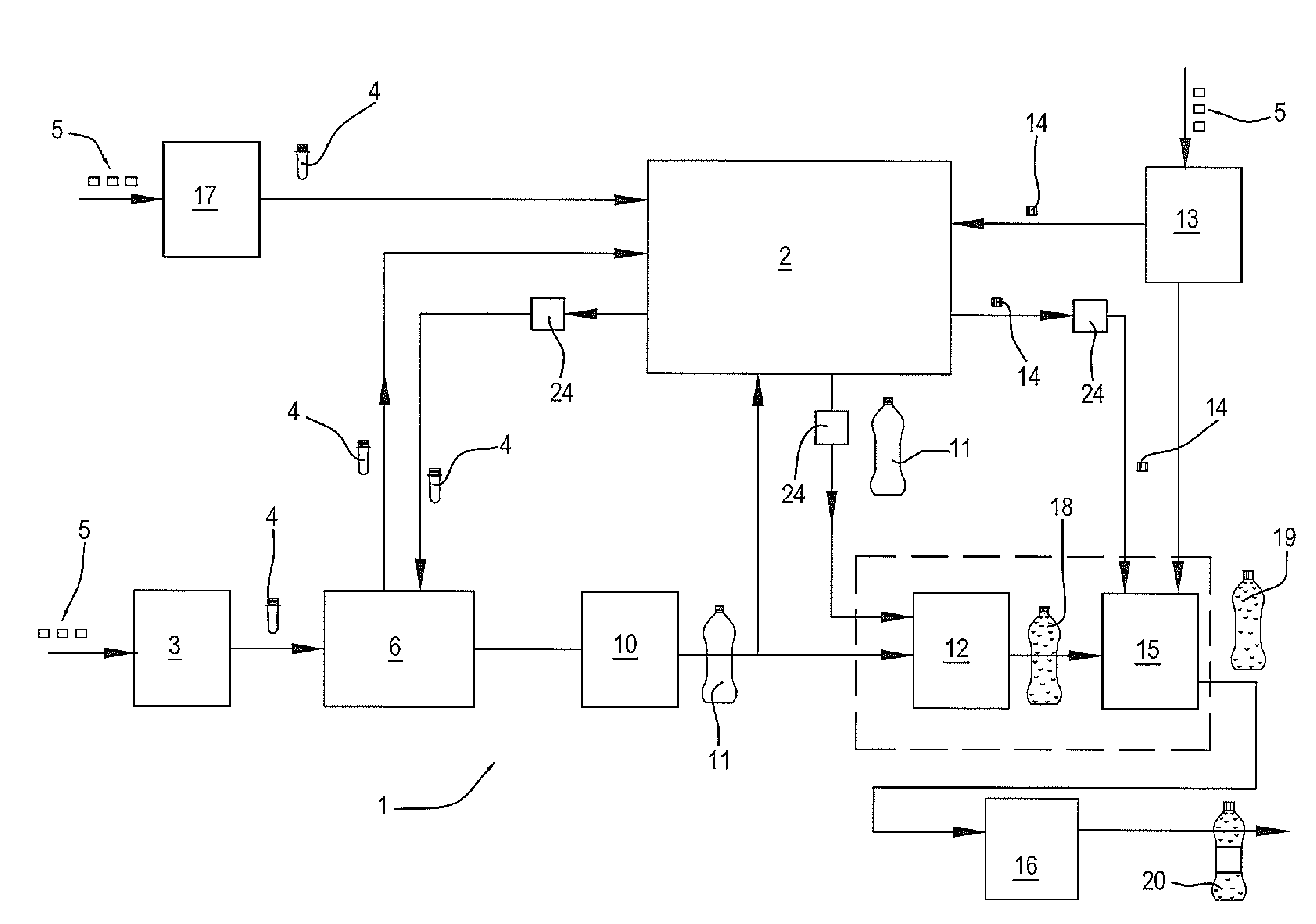
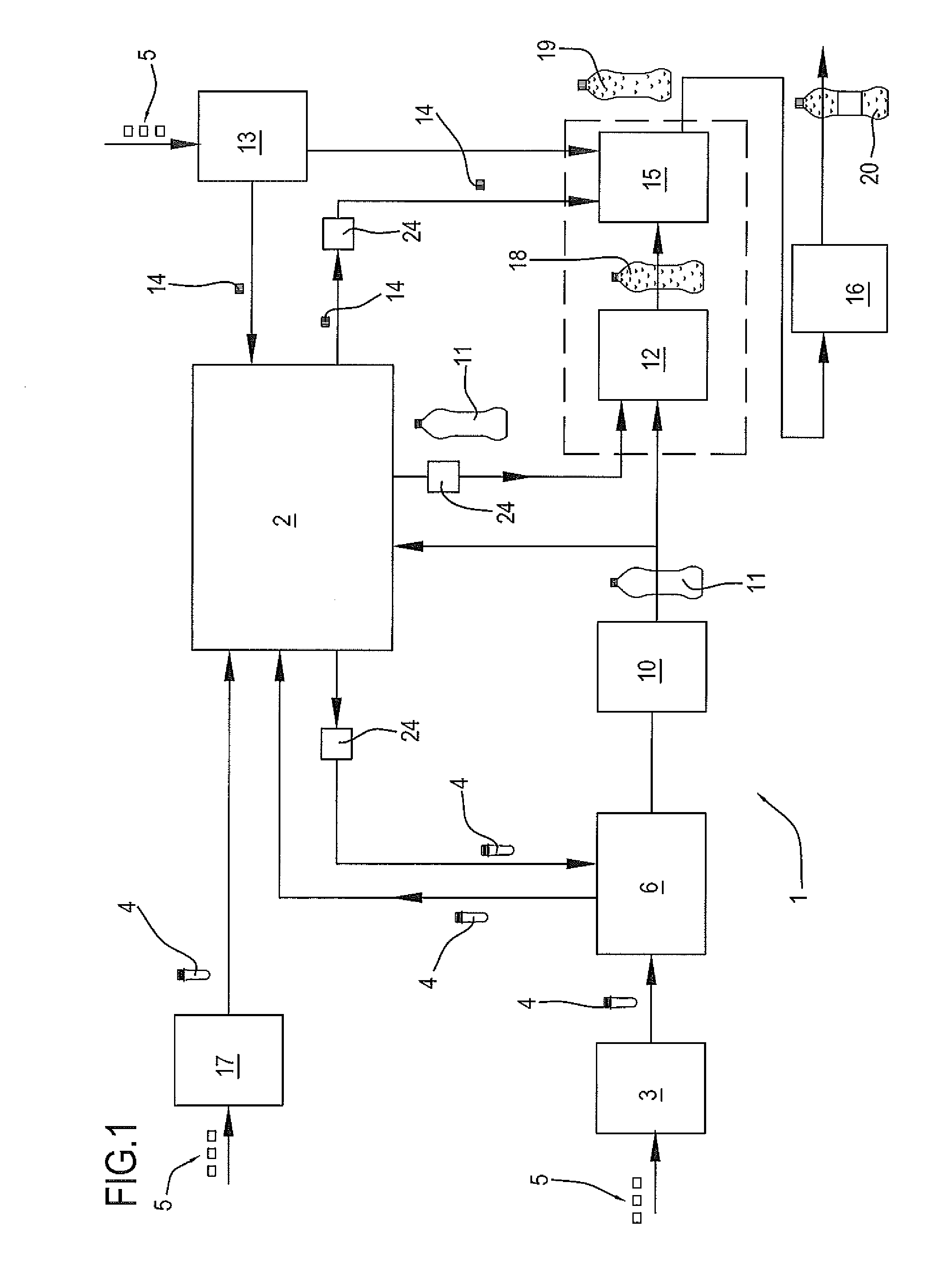
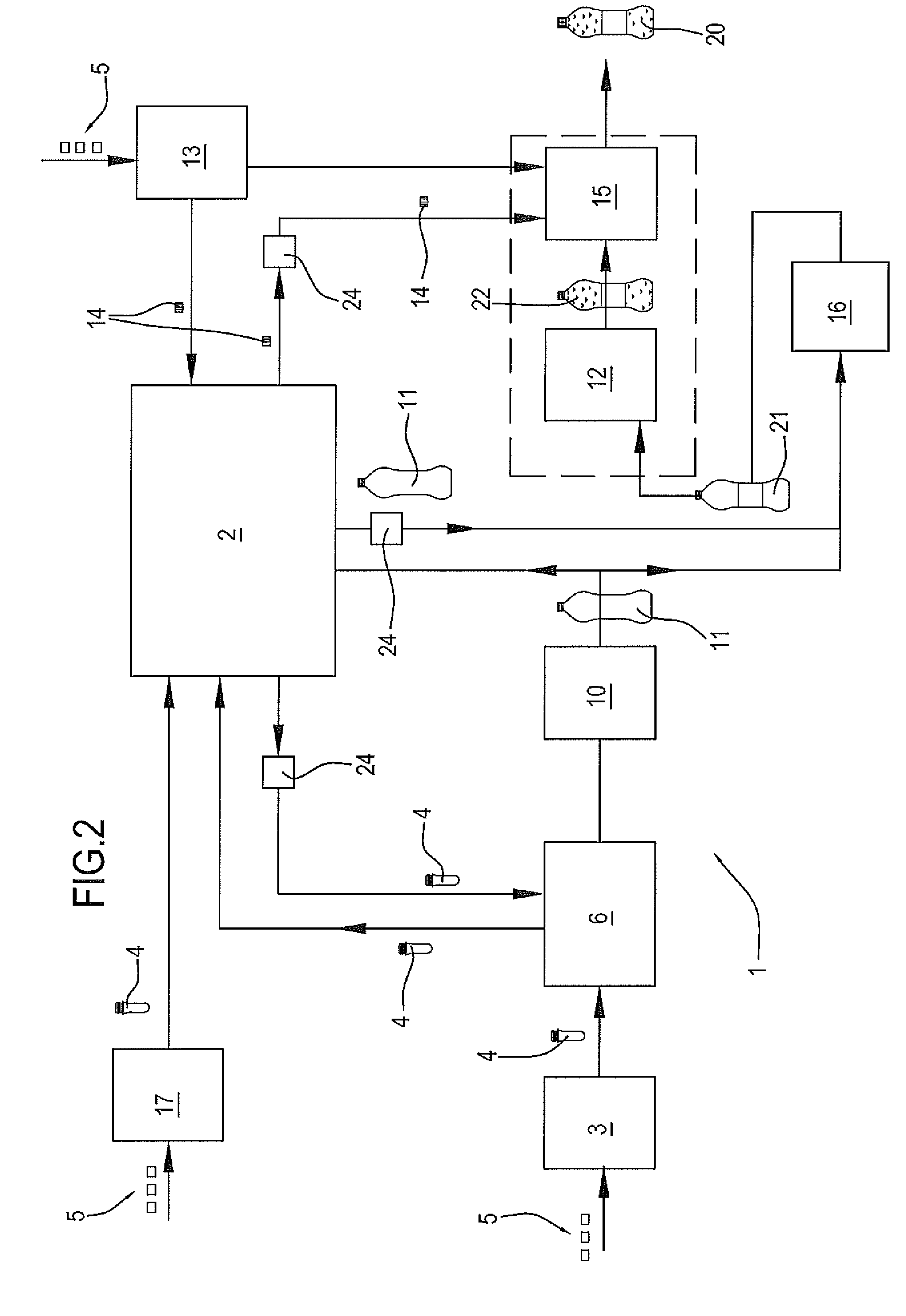
[0180]The numeral 1 in the drawings denotes a line (or plant) for bottling containers of thermoplastic material in continuous cycle.

[0181]The line 1 comprises a moulding unit 3 for making parisons 4 of thermoplastic material from the thermoplastic material in its raw form (for example, pellets 5 of raw, coloured plastic).

[0182]Preferably, the parison 4 moulding unit 3 is a rotary machine and, preferably, it works the plastic by compression.

[0183]The moulding unit 3 is described in detail in patent document WO2006092651 in the name of the same Applicant as this invention and incorporated herein by reference insofar as concerns the description of the rotary moulding machine.

[0184]The line 1 comprises a thermal conditioning unit 6 for the parisons 4.

[0185]The conditioning unit 6 is configured to receive the parisons from the moulding machine 3 and to heat the parisons 4.

[0186]The conditioning unit 6 is also configured to cool the parisons 4.

[0187]The conditioning unit 6 is configured i...


PUM

PropertyMeasurementUnit
Pressureaaaaaaaaaa

Abstract

A continuous cycle bottling line (1) for containers of thermoplastic material, comprises: a parison (4) moulding unit (3), a thermal conditioning unit (6) for the parisons (4); a blow-moulding unit (10); a filling unit (12) configured to receive the blow-moulded containers (11) from the blow-moulding unit (10) and to fill them with liquid or semi-liquid food products; a moulding unit (13) for making caps (14) of plastic material; a capping unit (15); a storage system (2) which is configured to contain the parisons (4) and the caps (14), which is interconnected with the units making up the line, and which defines inside it a controlled-atmosphere environment; the line defines an integrated system where the connections of the different units with each other and with the storage system (2) are located in a controlled-atmosphere environment.

Description

TECHNICAL FIELD[0001]This invention relates to a continuous cycle line and method for bottling containers of thermoplastic material.[0002]More specifically, the invention relates to a line and a method for making containers of thermoplastic material from raw plastic and filling them with liquid or semi-liquid food products.[0003]These bottling lines comprise:[0004]a moulding unit for making parisons of thermoplastic material from the thermoplastic material in its raw form;[0005]a parison thermal conditioning unit configured to receive the parisons from the moulding machine and to heat the parisons;[0006]a blow-moulding unit configured to receive the heated parisons from the conditioning unit and to blow-mould them into the moulds in such a way as to make containers designed to be filled with liquid or semi-liquid food products;[0007]a filling unit configured to receive the containers from the blow-moulding machine and to fill them with liquid beverages;[0008]a moulding unit for maki...

Claims


Application Information

Patent Timeline
IPC IPC(8): B65B3/02B65B7/28B65B3/04
CPCB65B3/022B65B7/28B65B3/04B65G1/06B29C49/06B29C49/36B29C49/4205B29C49/46B29C49/6418B29C49/6427B29C49/68B29C2049/028B29C2049/4697B29L2031/565B29L2031/7158B65G37/00B65G47/00B65G65/00B65G65/23B67C7/002B67C7/0073B67C2003/227
Inventor MARASTONI, DANIELE
Owner SACMI COOP MECCANICI IMOLA S C R L
Learn More