
Process And Apparatus For The Separation Of Air By Cryogenic Distillation

Inactive Publication Date: 2014-10-30
LAIR LIQUIDE SA POUR LETUDE & LEXPLOITATION DES PROCEDES GEORGES CLAUDE
View PDF5 Cites 2 Cited by
  • Summary
  • Abstract
  • Description
  • Claims
  • Application Information

AI Technical Summary

Benefits of technology

The invention provides a process for separating air by cryogenic distillation using a column system including a high pressure column, a low pressure column, an intermediate pressure column, and an argon column. The process involves cooling and pressurizing the air, and using heat exchangers to partially vaporize the air and separate it from other components. The process allows for the efficient separation of air into its main components, such as nitrogen and oxygen, with high purity. The invention also provides an apparatus for carrying out the process. The technical effects of the invention include improved air separation efficiency and purity, as well as reduced energy consumption and improved process economics.

Problems solved by technology

However, by liquefying important quantity of feed air, the high pressure column of the double column process is deprived of gaseous feed air such that its ability to provide the liquid reflux for the low pressure column is adversely affected.
The distillation performance will suffer when both liquid oxygen and liquid nitrogen in significant quantities are pumped by condensing air.
A loss of oxygen recovery will therefore occur.
However, in situations where both liquid oxygen and liquid nitrogen are vaporized, and sometimes with a liquid production requirement, too much liquid air is formed such that the quantity of rich liquid at the bottom of the high pressure column is sharply reduced.
Because of this effect, the use of intermediate pressure column with argon column becomes less effective or not practical for the simple reason that there is not sufficient liquid rich to drive the argon and intermediate pressure columns.
This mixing can introduce irreversibility in the distillation system and cause a loss of efficiency.

Method used


Image

  • Process And Apparatus For The Separation Of Air By Cryogenic Distillation
  • Process And Apparatus For The Separation Of Air By Cryogenic Distillation
  • Process And Apparatus For The Separation Of Air By Cryogenic Distillation

Examples


Embodiment Construction

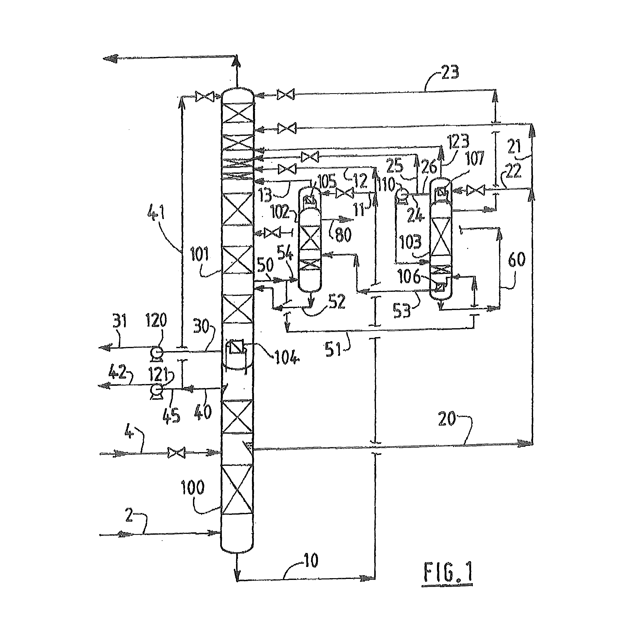
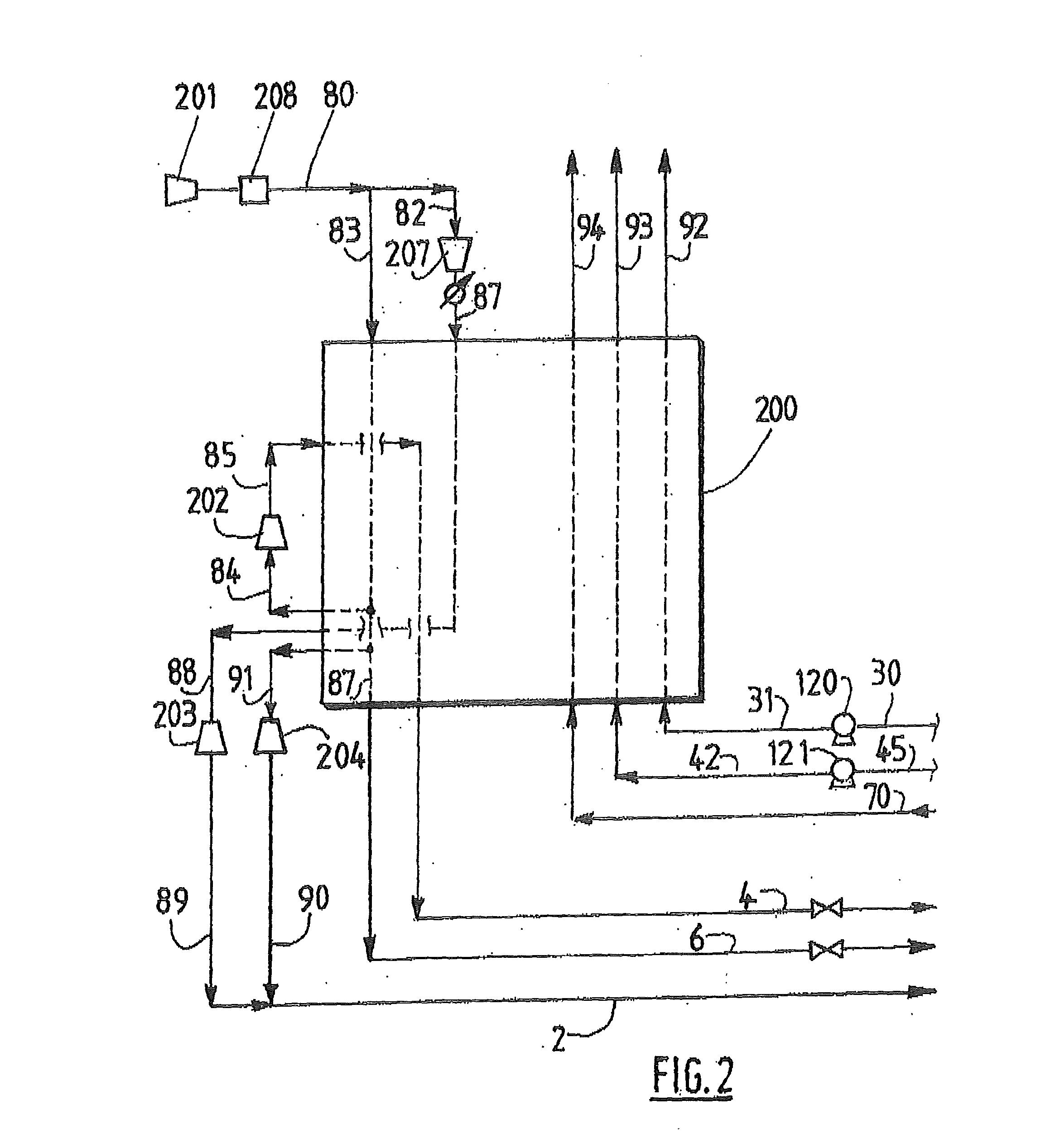
[0051]To illustrate the invention, FIG. 1 shows the column portion of a process operating according to an embodiment of the invention and FIGS. 2 and 3 show two alternative corresponding heat exchanger portions, to be used for oxygen pressures above 15 bars abs.

[0052]In FIG. 1, gaseous air 2 and liquid air 4 are fed to high pressure column 100. Oxygen enriched liquid 10 formed at the bottom of the high pressure column 100 is divided in two. One portion 12 is expanded and sent to an intermediate level of the low pressure column 101. Another portion 11 is expanded and sent to top condenser 105 of the argon column where it vaporizes to form stream 13 which is sent to the low pressure column 101. Alternatively all the oxygen enriched liquid 10 can be sent to the condenser 105 and partially condensed. In this case, stream 12 is absent and liquid from condenser 105 is sent to the low pressure column 101. The top of the high pressure column 100 is thermally coupled to the bottom of the low...


PUM


Abstract

An apparatus for the separation of air by cryogenic distillation comprises a column system including a double column, an intermediate pressure column, and an argon column having a top condenser, a heat exchanger, means for pressurizing and vaporizing oxygen rich liquid and nitrogen rich liquid from the double column, conduits configured to: send argon enriched gas from the low pressure column to the argon column, remove argon rich fluid from the top of the argon column, send a liquid air stream at least in part to a top condenser of the intermediate pressure column where it is partially vaporized to form a vapor and a liquid, send the vapor formed in the top condenser of the intermediate pressure column to the low pressure column, and send the liquid from the top condenser of the intermediate pressure column to the intermediate pressure column to be separated.

Description

CROSS REFERENCE TO RELATED APPLICATIONS[0001]This application is a §371 of International PCT Application PCT / EP2012 / 068948, filed Sep. 26, 2012, which claims the benefit of EP11306552.8, filed Nov. 24, 2011, both of which are herein incorporated by reference in their entireties.TECHNICAL FIELD OF THE INVENTION[0002]The present invention relates to a process and apparatus for the separation of air by cryogenic distillation.BACKGROUND[0003]Most oxygen plants are based on the LOX pumped cycle wherein liquid oxygen is pressurized by pump and vaporized by condensing pressurized air and then warmed to form the pressurized gaseous oxygen product. Usually about 25 to 35% of the feed air is liquefied by vaporizing the oxygen product. The liquid pumped cycle is not only applied for liquid oxygen but some liquid nitrogen can also be vaporized as well based on the same concept. When both liquid oxygen and liquid oxygen are pumped and vaporized by condensing air to form pressurized oxygen and ni...

Claims


Application Information

Patent Timeline
IPC IPC(8): F25J3/04
CPCF25J3/04F25J3/04054F25J3/04084F25J3/0409F25J3/04175F25J3/04296F25J3/04393F25J3/04448F25J3/04709
Inventor HA, BAOBRUGEROLLE, JEAN-RENAUD
Owner LAIR LIQUIDE SA POUR LETUDE & LEXPLOITATION DES PROCEDES GEORGES CLAUDE
Features
  • Generate Ideas
  • Intellectual Property
  • Life Sciences
  • Materials
  • Tech Scout
  • Unparalleled Data Quality
  • Higher Quality Content
  • 60% Fewer Hallucinations
Learn More