Methods for modifying multi-mode optical fiber manufacturing processes

a multi-mode optical fiber and manufacturing process technology, applied in the direction of manufacturing tools, optical apparatus testing, instruments, etc., can solve the problem that conventional fiber manufacturing processes may not consistently produce fiber that satisfies desired performance characteristics, and achieves the effect of maximizing the bandwidth function

Active Publication Date: 2014-10-30
CORNING INC
View PDF4 Cites 15 Cited by
  • Summary
  • Abstract
  • Description
  • Claims
  • Application Information

AI Technical Summary

Benefits of technology

[0009]In another embodiment, a method for adjusting at least one drawing process parameter in a process for manufacturing multi-mode optical fiber includes coupling light emitted from at least one light source at a plurality of wavelengths into a multi-mode optical fiber, and determining a plurality of corresponding bandwidths for light emitted at the plurality of wavelengths. Each wavelength is associated with a corresponding bandwidth. The method further includes determining a bandwidth function that fits...

Problems solved by technology

However, conventional fiber manufacturing processes may not consistently produce fiber that satisfies desired performance characteristics, ...

Method used


Image

  • Methods for modifying multi-mode optical fiber manufacturing processes
  • Methods for modifying multi-mode optical fiber manufacturing processes
  • Methods for modifying multi-mode optical fiber manufacturing processes

Examples


example 1

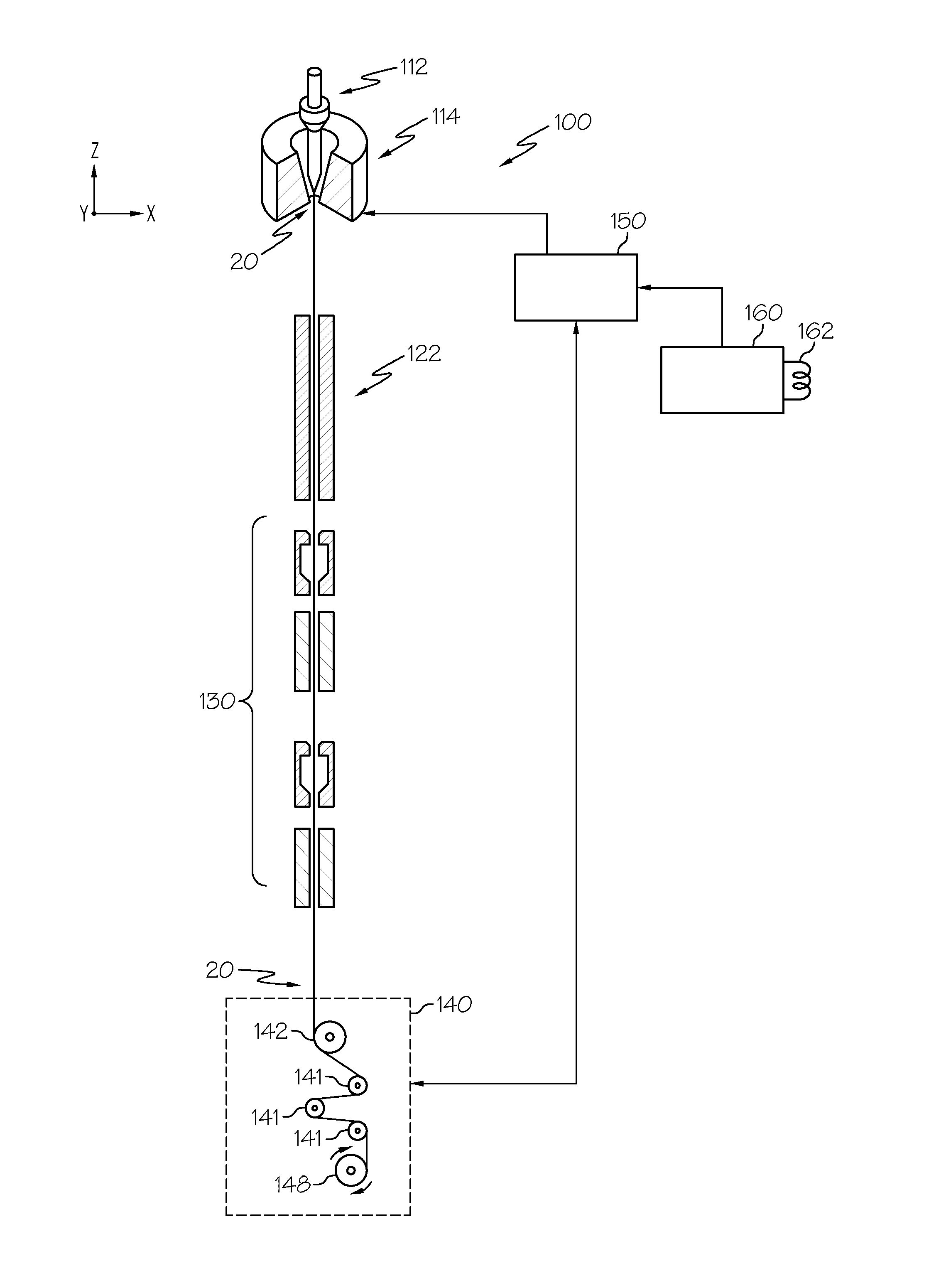
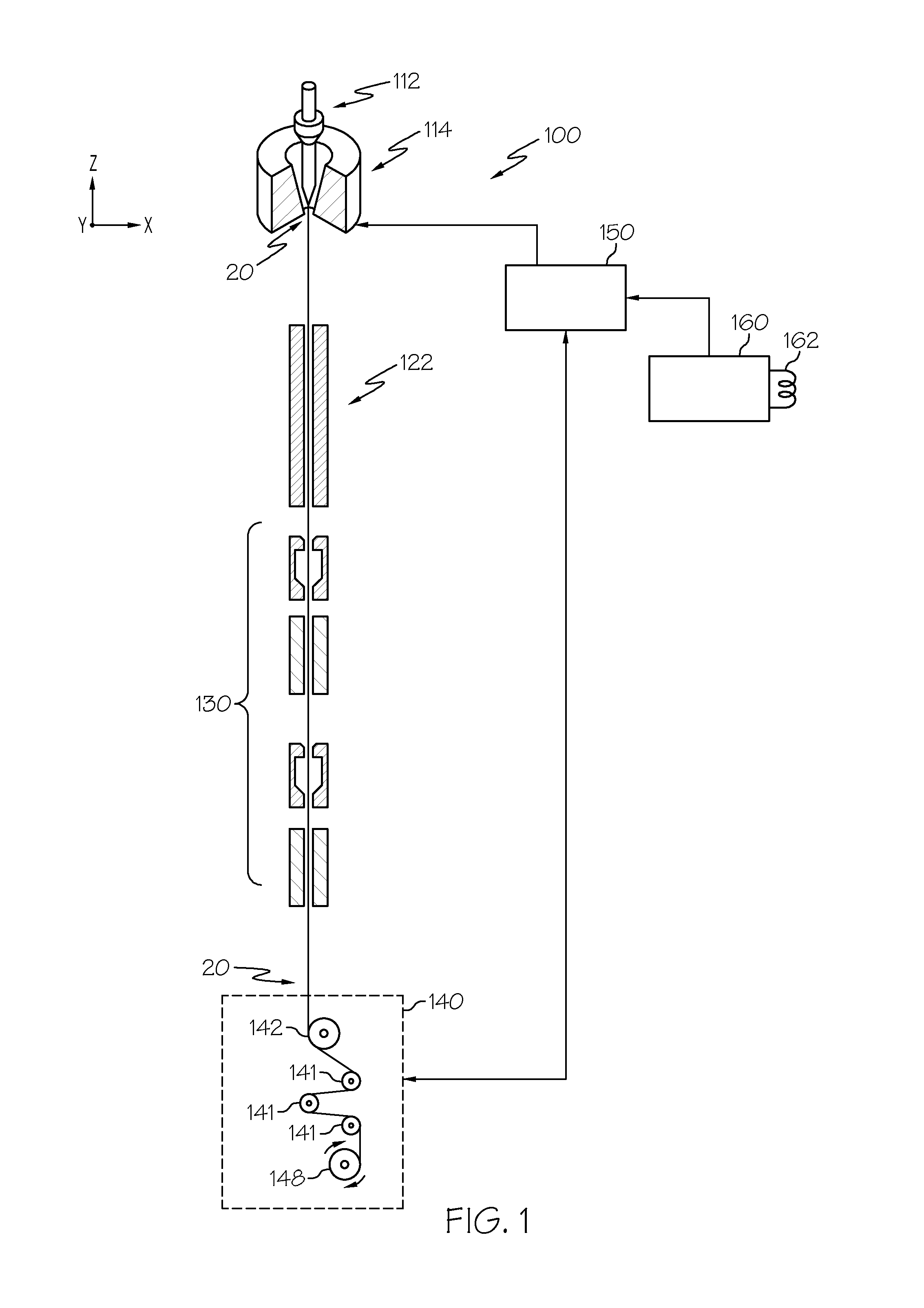
[0072]In one example, a number of multi-mode optical fibers were drawn at different drawing tensions, the measured peak wavelength of each of the four drawn multi-mode optical fibers was determined, a function defining the relationship between drawing tension and peak wavelength was established, the measured peak wavelength of a test segment of drawn fiber was determined, a difference between a target peak wavelength and the measured peak wavelength of the test segment was determined, and the process for manufacturing multi-mode optical fiber was modified based on the difference between the target peak wavelength and the measured peak wavelength, as will be described in further detail below.

[0073]As noted above, in this example, a number of multi-mode optical fibers were drawn at different drawing tensions. Four multi-mode optical fibers were drawn at a draw speed of about 70 meters per minute. The drawing tension of each of the four multi-mode optical fibers was adjusted by adjusti...

example 2

[0077]In another example, a number of optical fibers were drawn to have peak wavelengths at several target peak wavelengths. The modal bandwidth of each of the fibers was measured using a ModCon multimode fiber conditioner, commercially available from Ardent, which creates a typical multimode fiber launch condition as typically seen in VCSEL-based laser sources. To evaluate the ability to achieve various target peak wavelengths, drawing tensions were adjusted based on a function that defines the relationship between the change in drawing tension and the change in peak wavelength. The function defining the relationship between the change in drawing tension and change in peak wavelength may be any of the functions described above, or any other mathematical or empirical relation that maps target peak wavelength to drawing tension. The peak wavelength of each of the fibers was then measured to determine how close the measured peak wavelength was to the target peak wavelength. Specifical...

example 3

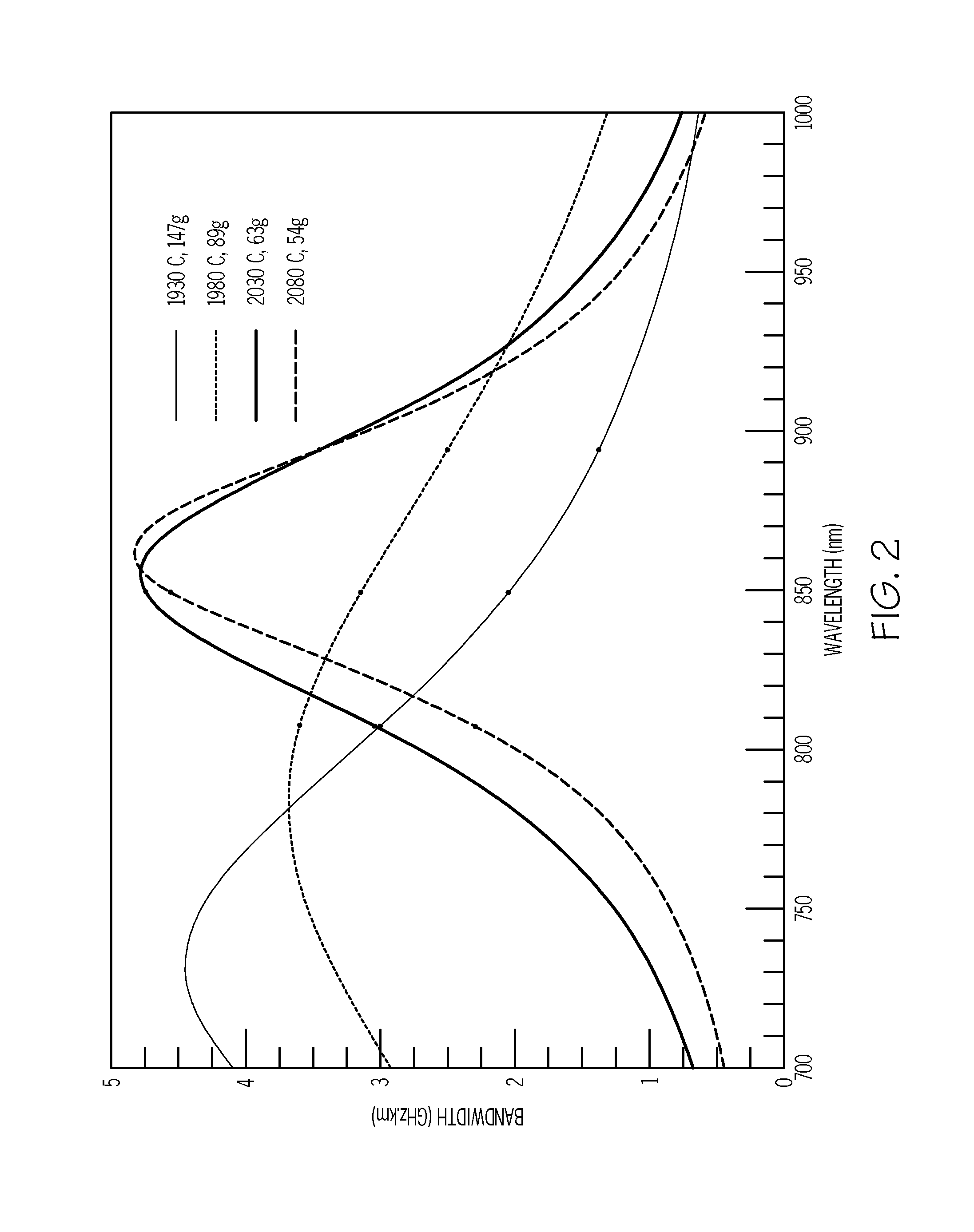
[0078]In another example using another preform, a fiber was drawn at a specified drawing tension of 147 g. After 20 km of the fiber was drawn, a first 1 km fiber sample was taken and the peak wavelength was measured to be 848 nm with peak bandwidth of 7.18 GHz*km and bandwidth at 850 nm to be 7.16 GHz*km. The draw tension was reduced by 17 g tension (to 130 g), resulting in a target peak wavelength of 873 nm. The peak wavelength of the fiber was measured to be 871 nm for a second 1 km sample after the adjustment in the tension. The measured peak wavelength of 871 nm is within 2 nm of the target peak wavelength, demonstrating the ability to tightly control peak wavelength. The peak bandwidth of the second fiber sample was 8.13 GHz*km with a bandwidth at 850 nm of 6.62 GHz*km. The draw tension was then increased by 14 g (to 144 g), resulting in a target peak wavelength of 850 nm. After waiting a few minutes to allow the tension to stabilize, a third 1 km sample fiber was taken, the pe...


PUM

PropertyMeasurementUnit
Wavelengthaaaaaaaaaa
Temperatureaaaaaaaaaa

Abstract

Methods for modifying multi-mode optical fiber manufacturing processes are disclosed. In one embodiment, a method for modifying a process for manufacturing multi-mode optical fiber includes measuring at least one characteristic of a multi-mode optical fiber. The at least one characteristic is a modal bandwidth or a differential mode delay at one or more wavelengths. The method further includes determining a measured peak wavelength of the multi-mode optical fiber based on the measured characteristic, determining a difference between the target peak wavelength and the measured peak wavelength, and modifying the process for manufacturing multi-mode optical fiber based on the difference between the target peak wavelength and the measured peak wavelength.

Description

CROSS-REFERENCE TO RELATED APPLICATIONS[0001]This application claims the benefit of priority under 35 U.S.C. §119 of U.S. Provisional Application Ser. No. 61 / 817,503 filed on Apr. 30, 2013 which application is incorporated herein by reference.BACKGROUND[0002]1. Field[0003]The present specification generally relates to optical fiber manufacturing processes and, more specifically, to methods for modifying multi-mode optical fiber manufacturing processes.[0004]2. Technical Background[0005]Manufacturing processes for producing multi-mode optical fiber typically include drawing multi-mode optical fiber from a glass perform that is heated in a draw furnace, cooling the drawn fiber, and coating the fiber after it has sufficiently cooled. Multi-mode optical fiber is typically produced to satisfy certain performance characteristics, such as for the drawn optical fiber to possess a threshold bandwidth for light emitted at a particular wavelength. The process parameters employed by the fiber m...

Claims


Application Information

Patent Timeline
IPC IPC(8): C03B37/025G01M11/00
CPCG01M11/30C03B37/0253G01M11/338G02B6/0288C03B2205/40
Inventor BOWKER, JENNIFERSUE A.CHEN, XINHURLEY, JASON EDWARDKLEMO, ELIOSMEJOUEV, IGOR RAFAELYEVICHNOLAN, DANIEL ALOYSIUSPOWERS, DALE ROBERT
Owner CORNING INC
Why Eureka
Try Eureka