Aircraft window and aircraft

a technology for aircraft and windows, applied in the field of aircraft windows, can solve the problems that wet-type conductive paint, such as a conductive sealant, is not suitable for the application, and achieves the effects of preventing electromagnetic noise, preventing electromagnetic noise invasion, and low cos

Active Publication Date: 2014-10-30
MITSUBISHI AIRCRAFT
View PDF19 Cites 26 Cited by
  • Summary
  • Abstract
  • Description
  • Claims
  • Application Information

AI Technical Summary

Benefits of technology

[0023]According to the present invention, the RF skin current or charged static can be more reliably passed to the airframe structure side while preventing electromagnetic noise by the electromagnetic shielding window and the conductive gasket seal more reliably than ever before. Therefore, it is possible to prevent invasion of electromagnetic noise into the airframe and electro static discharge.
[0024]Moreover, according to the present invention, the electromagnetic noise preventing effect, and the electro static discharge suppressing effect can be easily obtained at low cost without causing an increase in weight.

Problems solved by technology

On the other hand, the wet-type conductive paint, such as a conductive sealant, is not so suitable for the application.

Method used


Image

  • Aircraft window and aircraft
  • Aircraft window and aircraft
  • Aircraft window and aircraft

Examples


example 1

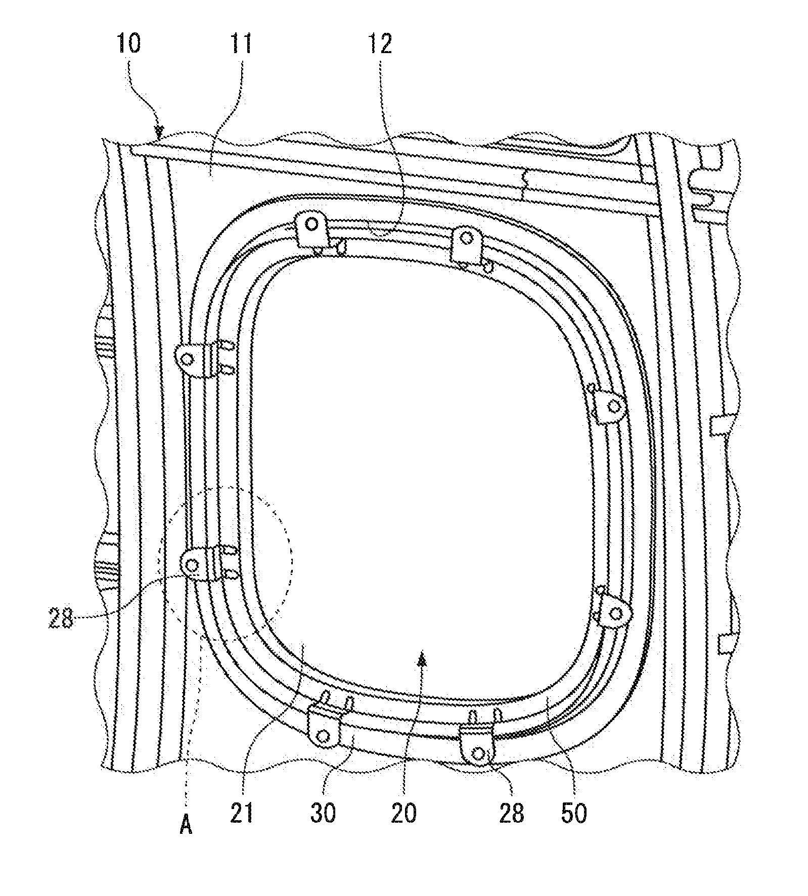
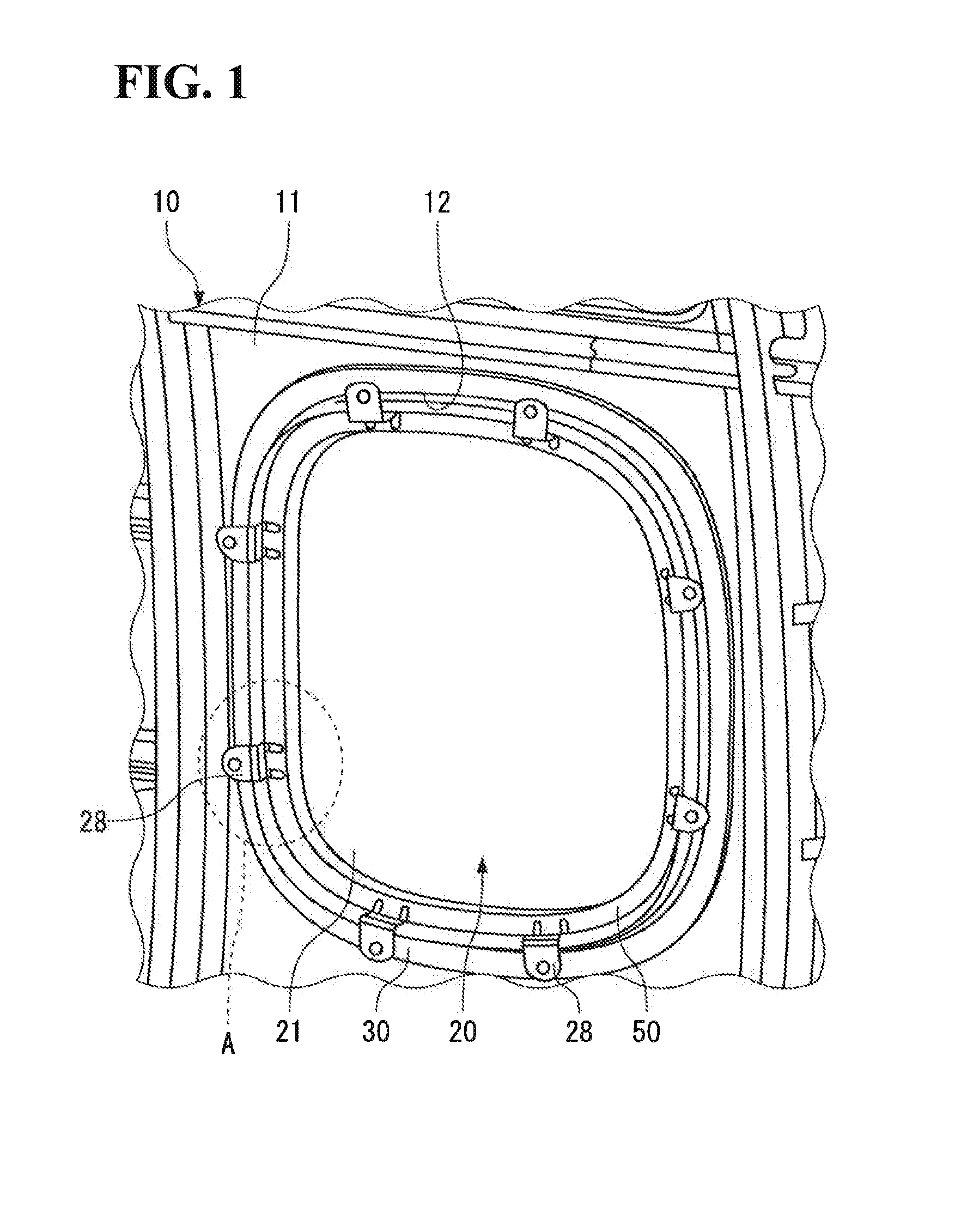
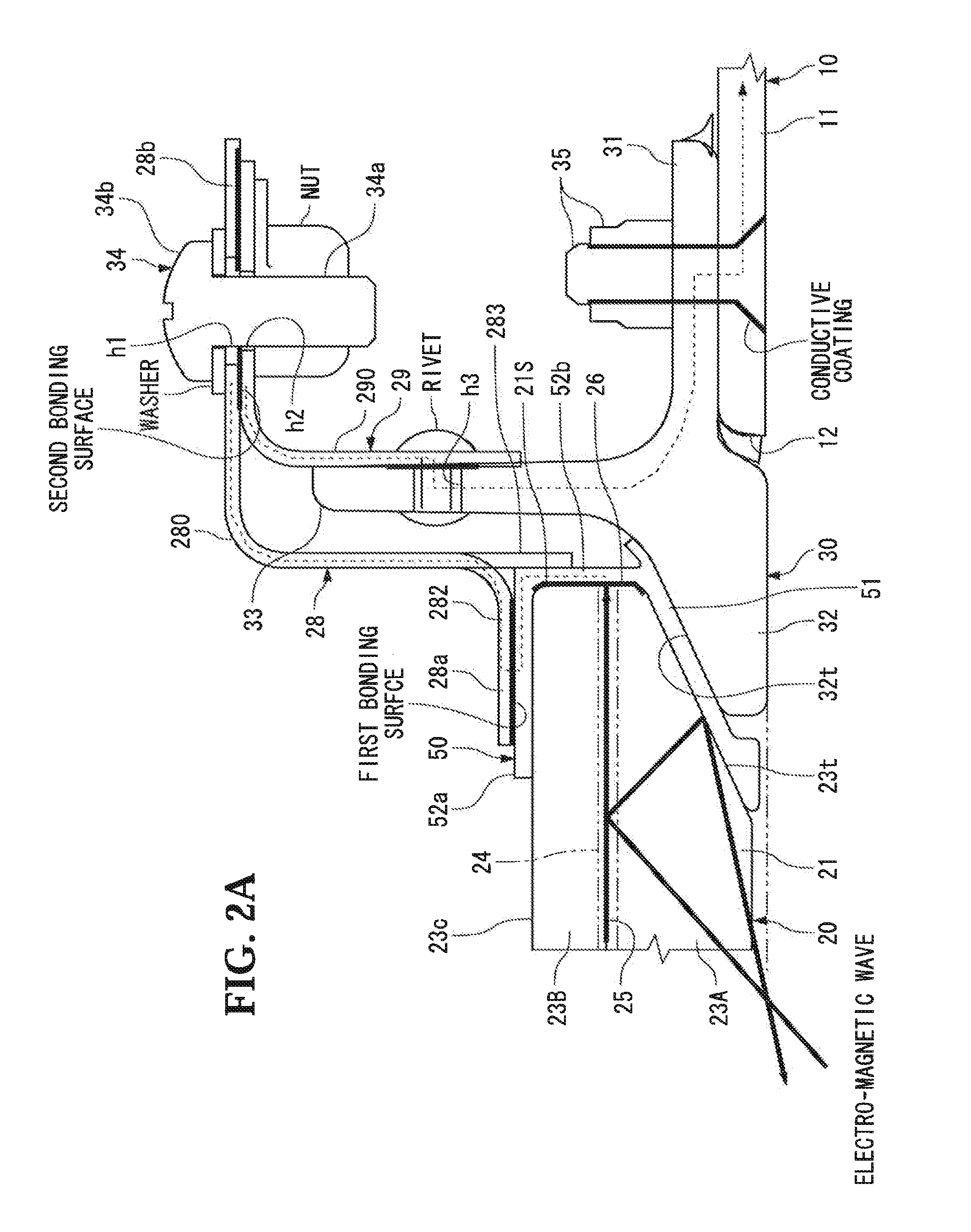
[0093]Examinations were carried out on the electromagnetic wave attenuation effect, with the volume resistivity of the gasket seal being changed. A gasket seal as shown in FIGS. 2A and 2B was provided on the outer perimeter of each of two acrylic plates having thicknesses t1=9.5 mm and t2=4 mm, and an external dimension of 248 mm×348 mm, and electromagnetic shielding effectiveness tests were carried out in accordance with IEEE STD-299-2006 “IEEE Standard Method for Measuring the Effectiveness of Electromagnetic Shielding Enclosures”. In this case, in addition to a gasket seal of a reference having no conductivity, gasket seals having a volume resistivity of 1.7 Ωcm (Measurement 1), that of 5 Ωcm (Measurement 2), that of 210 Ωcm (Measurement 3), and that of 310 Ωcm (Measurement 4) were prepared. Moreover, as the acrylic plate, except for comparative examples, shield mesh materials composed of polyester fibers of monofilaments copper-plated and black nickel-plated with a surface resis...

example 2

[0098]Next, examinations were carried out on the electromagnetic wave attenuation effect, with the electromagnetic shield mesh 25 being electrically bonded at a low impedance.

[0099]The electromagnetic shield mesh 25 as shown in FIG. 2A was arranged between two acrylic plates having thicknesses t1=8.1 mm and t2=4.6 mm, and an external dimension of 399 mm×327 mm, and electromagnetic shielding effectiveness tests were carried out in accordance with IEEE STD-299-2006 “IEEE Standard Method for Measuring the Effectiveness of Electromagnetic Shielding Enclosures”. A shield mesh obtained by stacking shield mesh materials composed of polyester fibers of monofilaments copper-plated and black nickel-plated with a surface resistivity of 0.15 Ω / square was used as the electromagnetic shield mesh 25.

[0100]As a result, as shown in FIGS. 10A and 10B, an attenuation effect of at least 20 dB or more against electromagnetic waves was obtained over the entire frequency bands from 100 MHz to 18 GHz in me...


PUM


Abstract

A window body constituting a window of an aircraft includes an electromagnetic shield film, and a conductive paint is applied to an outer perimeter edge face of the window body. A fixing member secures the window body to an airframe with a gasket seal and a window frame interposed therebetween. The fixing member has a first bonding surface on which a conductive film is formed. The first bonding surface is in direct contact with the gasket seal. An electrical path is formed through the electromagnetic shield film, the conductive paint, the gasket seal, the fixing member, and the window frame.

Description

CROSS-REFERENCE TO RELATED APPLICATIONS[0001]This application is a continuation in part of U.S. patent application Ser. No. 13 / 560,388 filed on Jul. 27, 2012 which is based on Japanese Patent Application No. 2011-200692 filed on Sep. 14, 2011. The contents of these applications are herein incorporated by reference in their entirety.BACKGROUND OF THE INVENTION[0002]1. Field of the Invention[0003]The present invention relates to an aircraft window having an electromagnetic shield and an aircraft including the same.[0004]2. Description of the Related Art[0005]Aircraft have to be able to fly in safety without occurrence of a malfunction, an unforeseen behavior (up-set), or others in High Intensity Radiated Fields (HIRF), which represents an electro-magnetic environment from radio, television, radar, emitters, and other sources during cruising flight or during takeoff or landing. To this end, HIRF protection measures required in (14 CFR) sections 23.1308, 25.1317, 27.1317, and 29.1317 of...

Claims


Application Information

Patent Timeline
Patent Type & Authority Applications(United States)
IPC IPC(8): B64C1/14B60J10/00B64D45/00
CPCB64C1/1492B60J10/0002B64D45/00B64C1/1484B60J10/16B64D45/0063
Inventor YOKOI, TAKASHI
Owner MITSUBISHI AIRCRAFT
Why Eureka
Try Eureka