
Piping connection structure

a technology of connection structure and pipe, which is applied in the direction of pipe couplings, machines/engines, couplings, etc., can solve the problems of increasing the amount of fuel permeation, reducing the thickness of the diameter-expanded portion of the resin tube, and so as to achieve the effect of increasing the elastic modulus, reducing the sealing performance, and improving the sealing performan

Active Publication Date: 2014-10-30
SUMITOMO RIKO CO LTD
View PDF1 Cites 16 Cited by
  • Summary
  • Abstract
  • Description
  • Claims
  • Application Information

AI Technical Summary

Benefits of technology

The invention relates to a resin tube used in a piping system. The resin tube has a tapered diameter-expanding portion and a cylindrical portion, which have the same or greater thickness than the tube body portion, to prevent deformation and maintain sealing performance. The tapered diameter-expanding portion has an increased elastic modulus to further suppress deformation. The inner side of the expansion portion is designed for smooth fuel flow. The amount of fuel permeation is insignificant due to the same thickness of the resin tube at the expansion portion compared to the tube body portion. A separate retainer is used to restrict the pipe body from coming off, improving durability. The engagement projections and recesses achieve reliable connection of the resin tube and the retainer.

Problems solved by technology

However, in the structures in which the pipe body is restricted by having the previously processed portion of the resin tube caught by the annular projection of the pipe body, that portion of the resin tube is deformed also in removing the pipe body.
If the diameter-expanded portion does not have a sufficiently high elastic modulus in such a case, the resin tube will be deformed and cause a decrease in sealing performance.
Therefore, a decrease in thickness of the diameter-expanded portion of the resin tube has a risk of increasing the amount of fuel permeation.

Method used


Image

  • Piping connection structure
  • Piping connection structure
  • Piping connection structure

Examples


example 1

Piping Connection Structure Overview

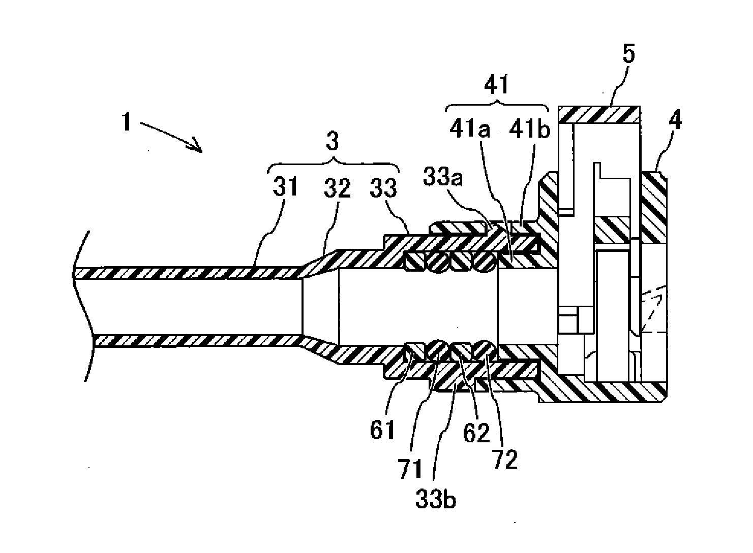
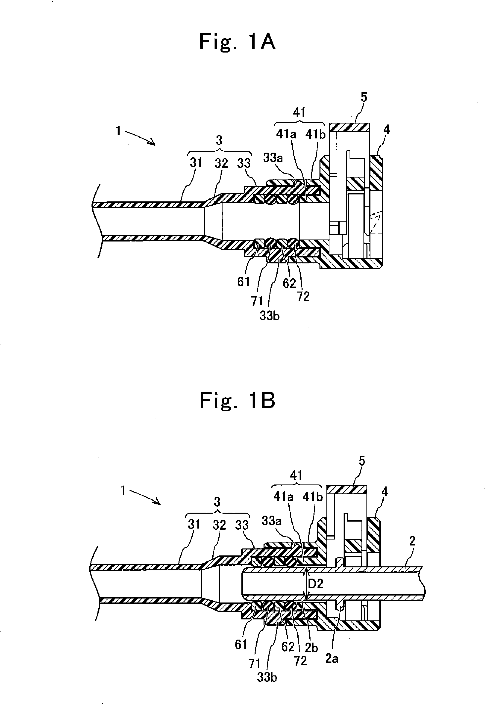
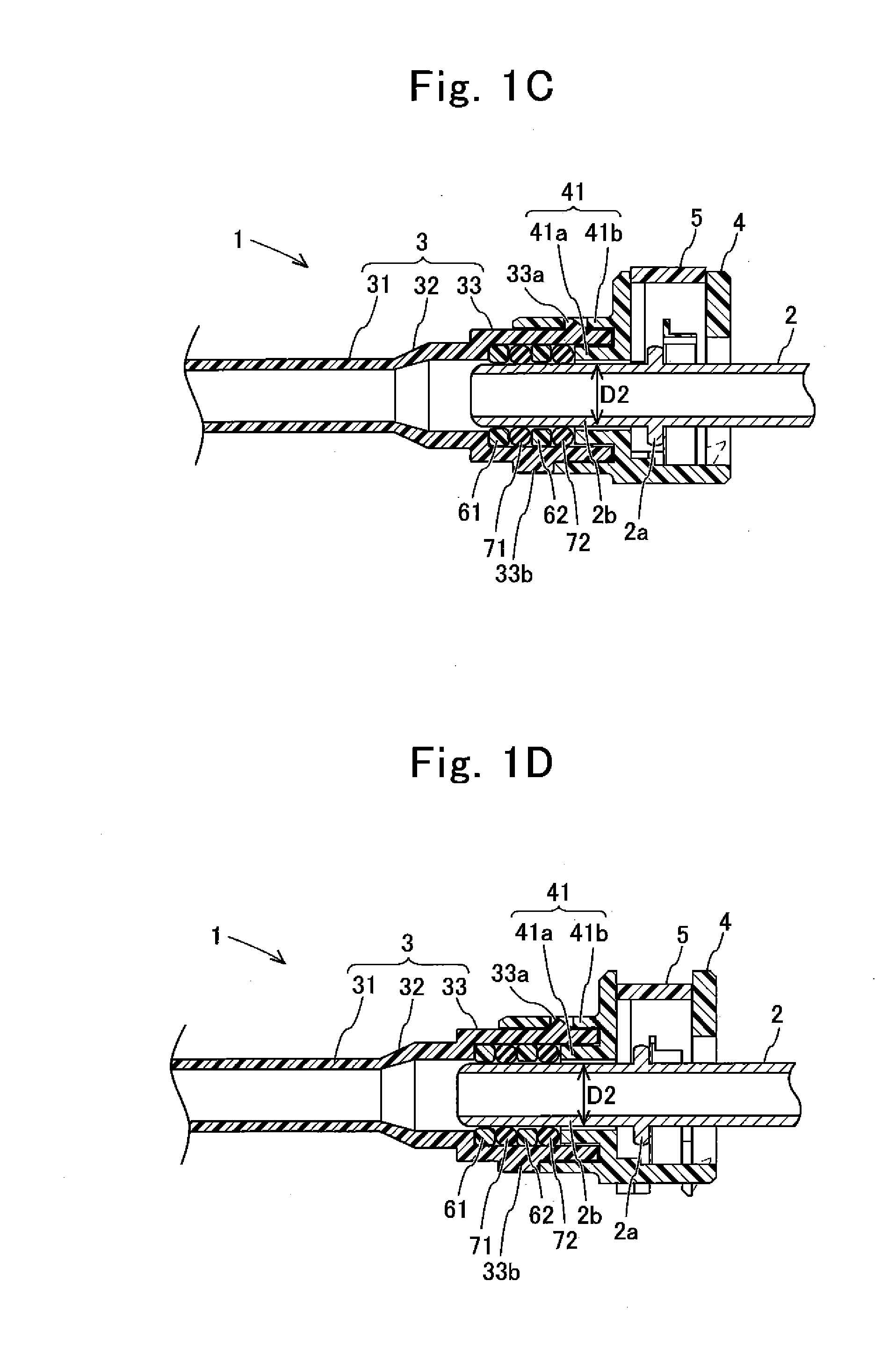
[0047]An overview of a piping connection structure of the present example will be described with reference to FIGS. 1A to 1D. As shown in FIG. 1C, the piping connection structure constitutes, for example, a gasoline fuel piping 1 of an automobile and corresponds to a portion for connecting a pipe body 2 and a resin tube 3. As shown in FIG. 1C, the piping 1 comprises the pipe body 2, the resin tube 3, a retainer 4, a checker 5, collars 61, 62 and seal members 71, 72.

[0048]As shown in an initial state view of FIG. 1A, the resin tube 3 and the retainer 4 are connected together, and the collar 61, the seal member 71, the collar 62, and the seal member 72 are arranged in this order in an inner circumferential surface side of the resin tube 3. Moreover, the checker 5 has been assembled to the retainer 4. From this state, the pipe body 2 is inserted in the retainer 4 as shown in a pipe body-inserted state view of FIG. 1B. At this time, a fore end side of...

example 2

[0098]A piping connection structure of Example 2 will be described with reference to FIG. 5. As shown in FIG. 5, a second diameter-expanding portion 33 of a resin tube 3 of this example does not have either the engagement portions 33a or the guide projections 33b of the above example. Moreover, a tube engagement portion 41 of a retainer 4 of this example does not have either the engagement recesses 41c or the guide recesses 41d of the above example. Since constitutional features other than the above are the same as those of Example 1, these are assigned with the same reference signs and their description is omitted.

[0099]In this example, the second diameter-expanding portion 33 and the tube engagement portion 41 are connected together not by physically catching each other but welding. Therefore, these two members do not have any projections or recesses but are connected together. Connecting these two members by welding in this way allows shape simplification of the second diameter-e...


PUM

PropertyMeasurementUnit
structureaaaaaaaaaa
distanceaaaaaaaaaa
diameteraaaaaaaaaa

Abstract

Provided is a piping connection structure which assigns a function to restrict a pipe body from coming off to a member other than a resin tube, improves in sealing performance and can suppress the amount of fuel permeation. A resin tube comprises a tube body portion; a first diameter-expanding portion formed to increase in diameter from an axial end of the tube body portion and axially positioning seal members by holding the seal members in an axial gap with a retainer; and a second diameter-expanding portion formed to further increase in diameter from the first diameter-expanding portion, and to contact an outer circumferential side of the seal members and be connected to the retainer while in contact with the retainer. Thickness of the first diameter-expanding portion is equal to or greater than thickness of the tube body portion.

Description

CROSS-REFERENCE TO RELATED APPLICATION[0001]This is a continuation of Application PCT / JP2013 / 081307, filed on Nov. 20, 2013, which is incorporated herein by reference.[0002]The present invention is based on Japanese Patent Application No. 2012-278342, filed on Nov. 20, 2012, the entire contents of which are incorporated herein by reference.BACKGROUND OF THE INVENTION[0003]1. Field of the Invention[0004]The present invention relates to a piping connection structure for connecting a resin tube and a pipe body.[0005]2. Description of the Related Art[0006]In recent years, it has been proposed to constitute part or all of the function of a connector with a resin tube in a piping connection portion in order to reduce size and costs of that portion. For example, PTLs 1 to 5 describe structures in which a seal member is disposed between a diameter-expanded portion of a resin tube and a pipe body by processing an end portion of the resin tube beforehand so as to expand its diameter. These do...

Claims


Application Information

Patent Timeline
Patent Type & Authority Applications(United States)
IPC IPC(8): F16L37/14
CPCF16L37/144F16L37/088F16L37/098F16L47/02F02M37/0017F16L2011/047F16L2201/10F16L37/0885
Inventor TAKIMOTO, YORIHIROMIZUTANI, KOJIKATAYAMA, KAZUTAKA
Owner SUMITOMO RIKO CO LTD
Learn More