Touch input system and method for detecting touch using the same

a technology of input system and touch detection, which is applied in the direction of instruments, computing, electric digital data processing, etc., can solve the problems of inability to distinguish between palm touch and stylus touch on the electrode, difficulty in sensing a change in mutual capacitance during the touch of the stylus, and directly affecting sensitivity, so as to reduce the size and manufacturing cost of the stylus

Active Publication Date: 2014-10-30
LG DISPLAY CO LTD
View PDF5 Cites 35 Cited by
  • Summary
  • Abstract
  • Description
  • Claims
  • Application Information

AI Technical Summary

Benefits of technology

[0020]An object of the present invention is to provide a touch input system and a touch detection method using the same, by which a stylus is implemented without a battery and the size and manufacturing costs of the stylus are reduced while stylus touch and finger touch are distinguished and detected.

Problems solved by technology

However, when the touch detection circuit of FIG. 1 is used for stylus touch instead of finger touch, since a contact area between a tip of the stylus and a sensor panel surface is relatively small, mutual capacitance variation ΔCm between electrodes is small, and thus, it is difficult to sense a change in mutual capacitance during the stylus touch.
When the tip of the stylus is small compared with an electrode formed on the sensor panel for sensing, coordinate distortion occurs according to presence of an electrode, thereby directly affecting sensitivity.
In addition, in cases of the finger touch and the stylus touch using the same touch detection circuit, when touch is input via the stylus, problems arise in that a palm touch and the stylus touch on the electrode cannot be distinguished.
That is, it is difficult to provide a palm rejection function during stylus touch to the detection circuit of FIG. 1.

Method used


Image

  • Touch input system and method for detecting touch using the same
  • Touch input system and method for detecting touch using the same
  • Touch input system and method for detecting touch using the same

Examples


Embodiment Construction

[0057]Reference will now be made in detail to the preferred embodiments of the present invention, examples of which are illustrated in the accompanying drawings.

[0058]A touch input system according to the present invention can detect finger touch via a basic structure for touch detection using a capacitive method, and detect stylus touch via resonance between an internal resonance circuit of the stylus and an antenna loop formed outside the edge of the sensor panel. There is a limit in detecting stylus touch using a capacitive method, and thus, the stylus touch can be detected by changing the structure outside the edge of the sensor panel and an internal circuit of the stylus without a separate panel irrespective a contact area or shapes of electrode patterns.

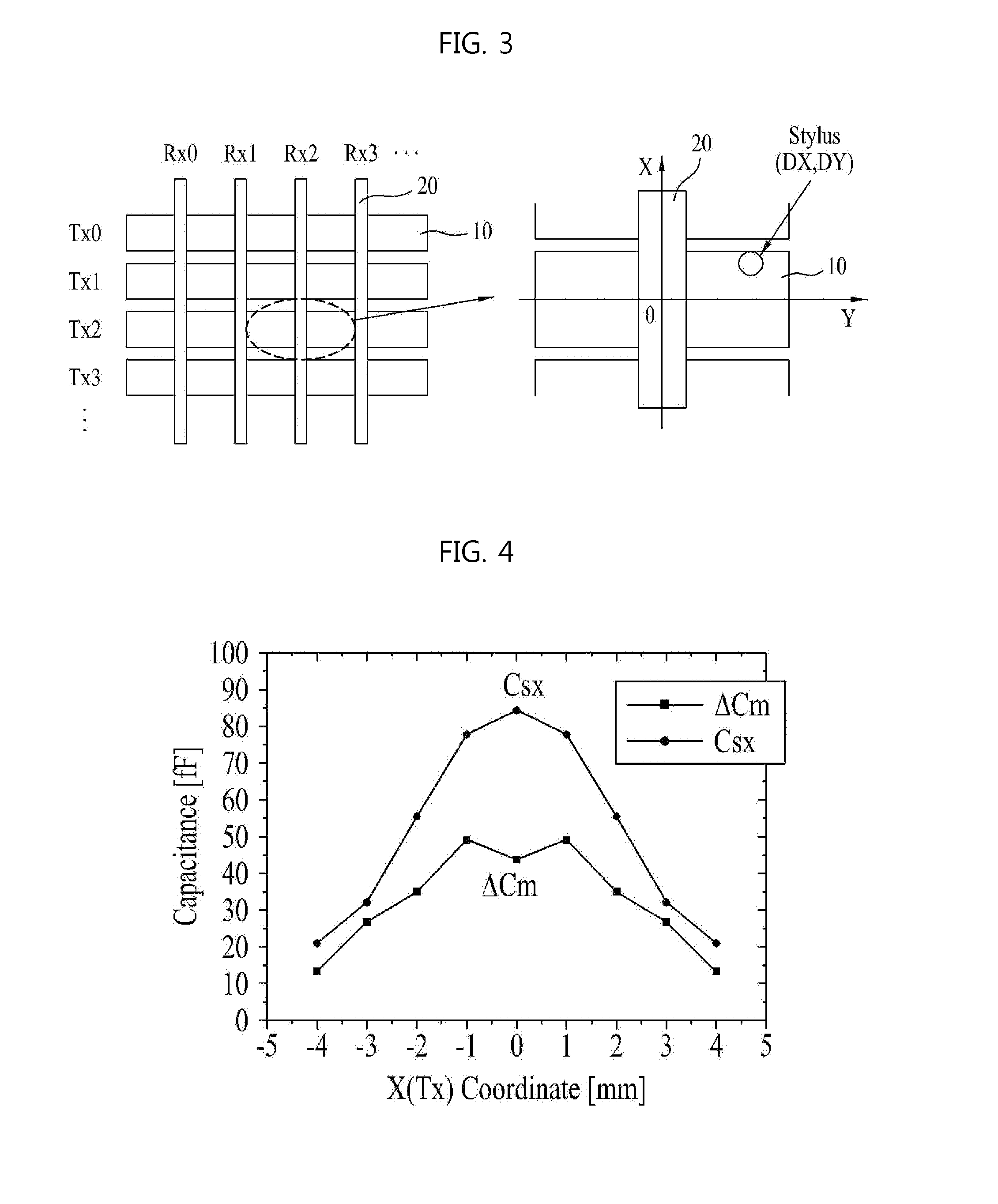
[0059]Hereinafter, a structure of a capacitive electrode formed in an active region and a phenomenon of stylus touch using the capacitive electrode will be described.

[0060]FIG. 3 is a plan view of a structure inside an active r...


PUM


Abstract

A touch input system and a touch detection method using the same are disclosed. With the disclosed touch input system, the size and manufacturing costs of the stylus are reduced while finger touch and touch of stylus without a battery are distinguished and detected. The touch input system includes a sensor panel including a plurality of first channels and a plurality of second channels, crossing each other, a stylus including one or a plurality of primary coils connected in series to each other, a resonance capacitor connected in parallel to the primary coil, and a conductive tip connected to the primary coil, a ground connected to the stylus, an antenna loop formed outside an edge of the sensor panel, and a touch controller connected to the first channel, the second channel, and the antenna loop.

Description

CROSS-REFERENCE TO RELATED APPLICATIONS[0001]The present invention claims the benefit of Korean Patent Application No. 10-2013-0048725, filed on Apr. 30, 2013, which is hereby incorporated by reference for all purposes as if fully set forth herein.BACKGROUND OF THE INVENTION[0002]1. Field of the Invention[0003]The present invention relates to a touch input system and a touch detection method using the same, by which the size and manufacturing costs of the stylus are reduced while finger touch and touch of stylus without a battery are distinguished and detected.[0004]2. Discussion of the Related Art[0005]With the advent of an increased information age, a display field for visually expressing electrical information signals has rapidly developed. To meet this trend, various flat display devices having excellent performance characteristics, i.e., miniaturized, lightweight, and low power consumption, have been developed.[0006]Examples of flat display devices may include liquid crystal di...

Claims


Application Information

Patent Timeline
Patent Type & Authority Applications(United States)
IPC IPC(8): G06F3/044G06F3/0354
CPCG06F3/03545G06F3/044G06F3/0416G06F3/046G06F2203/04106G06F3/0446G06F2203/04111
Inventor KIM, HA-ZOONG
Owner LG DISPLAY CO LTD
Why Eureka
Try Eureka