
Cavity enhanced absorption spectroscopy with a laser modulation side-band frequency locked to the cavity

a laser modulation side-band frequency and enhanced absorption technology, applied in the field of cavity enhanced absorption spectroscopy, can solve the problems of limiting the duty cycle of ceas measurement, waste of remaining laser power, and time-consuming sweeping

Active Publication Date: 2014-10-30
ENTANGLEMENT TECH
View PDF11 Cites 29 Cited by
  • Summary
  • Abstract
  • Description
  • Claims
  • Application Information

AI Technical Summary

Benefits of technology

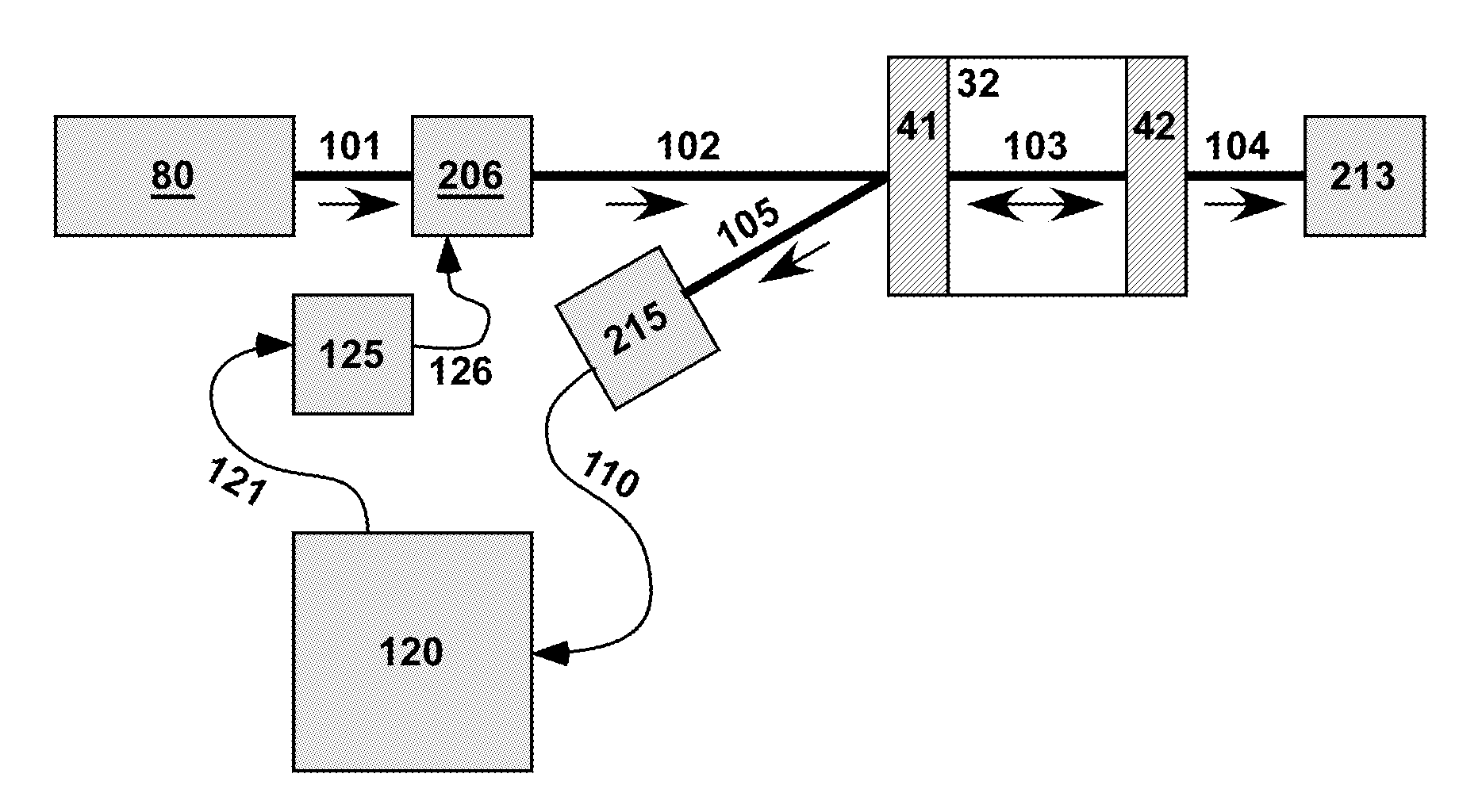
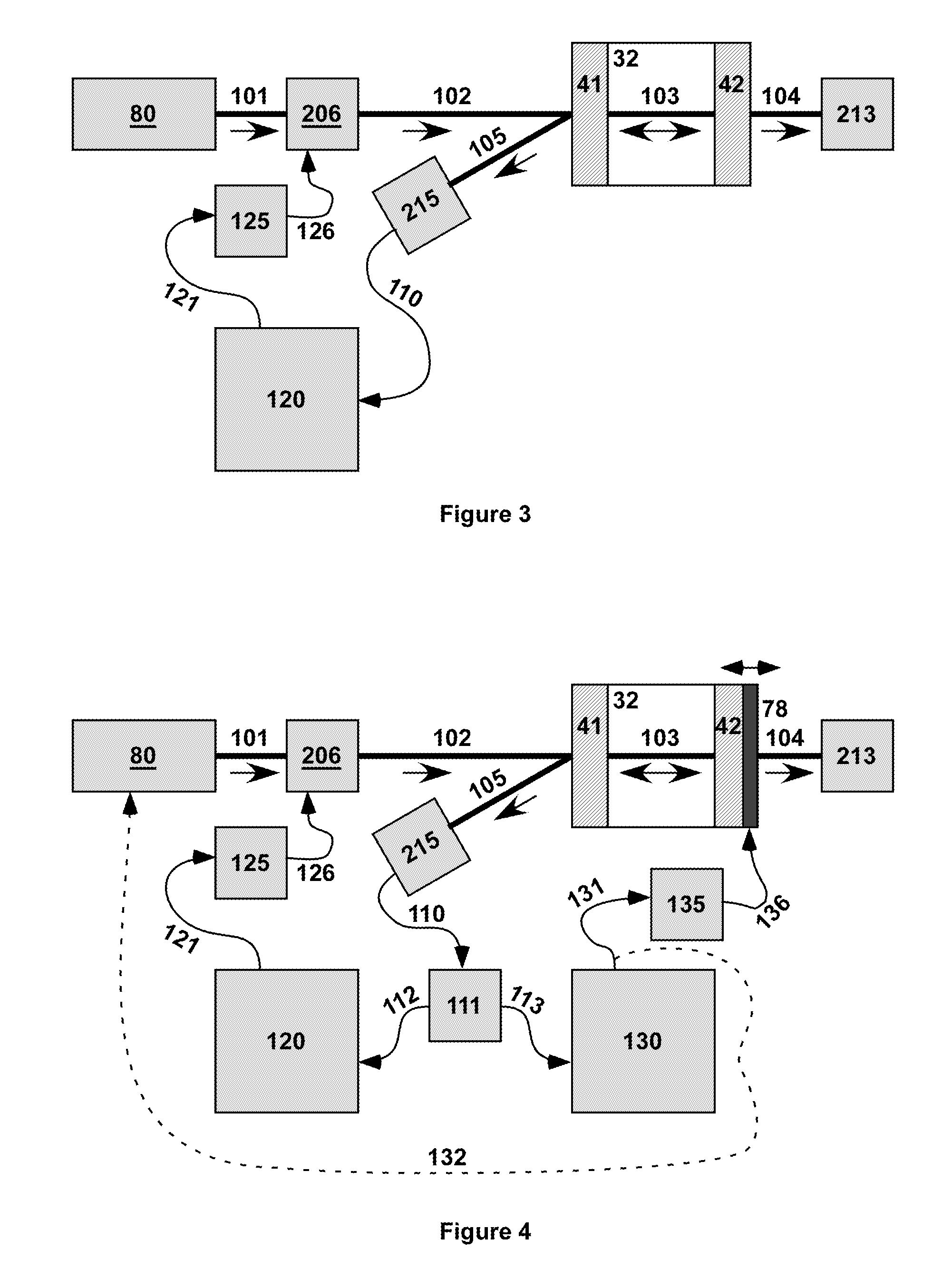
The present invention is a cavity enhanced absorption spectrometer that uses a modulator to create an electro-magnetic radiation sideband with a known frequency. This sideband is then injected into a cavity enhanced absorption resonator, which has a resonant frequency that needs to be adjusted to match the frequency of the sideband. The spectrometer uses a controller to adjust the frequency of the RF source or the resonant frequency of the cavity enhanced absorption resonator to maintain the predetermined proximity between the sideband and the resonator. This invention allows for more accurate and reliable measurements, even when lasers cannot respond quickly enough to maintain locking.

Problems solved by technology

Thus only a fraction of the laser power, namely the fraction within a CEAS resonator mode bandwidth (or within the bandwidths of several modes), is injected into the CEAS resonator, and the remaining laser power is wasted.
Sweeping takes time and limits the duty cycle of the CEAS measurement.
As in ORDS, sweeping either the wavelength or the cavity length takes time and limits the duty cycle of the measurement.
This fluctuation is typically dominated by laser frequency noise.
The optical frequency of most distributed feedback (DFB) lasers, however, does not respond quickly to current injection (1 MHz).
As a result, there is no direct adjustment of either the CEAS resonator or the laser in the high-frequency range to maintain locking.
This reduces the radiation injection efficiency and transient disturbance may cause total loss of lock, including at low frequency.

Method used


Image

  • Cavity enhanced absorption spectroscopy with a laser modulation side-band frequency locked to the cavity
  • Cavity enhanced absorption spectroscopy with a laser modulation side-band frequency locked to the cavity
  • Cavity enhanced absorption spectroscopy with a laser modulation side-band frequency locked to the cavity

Examples


Embodiment Construction

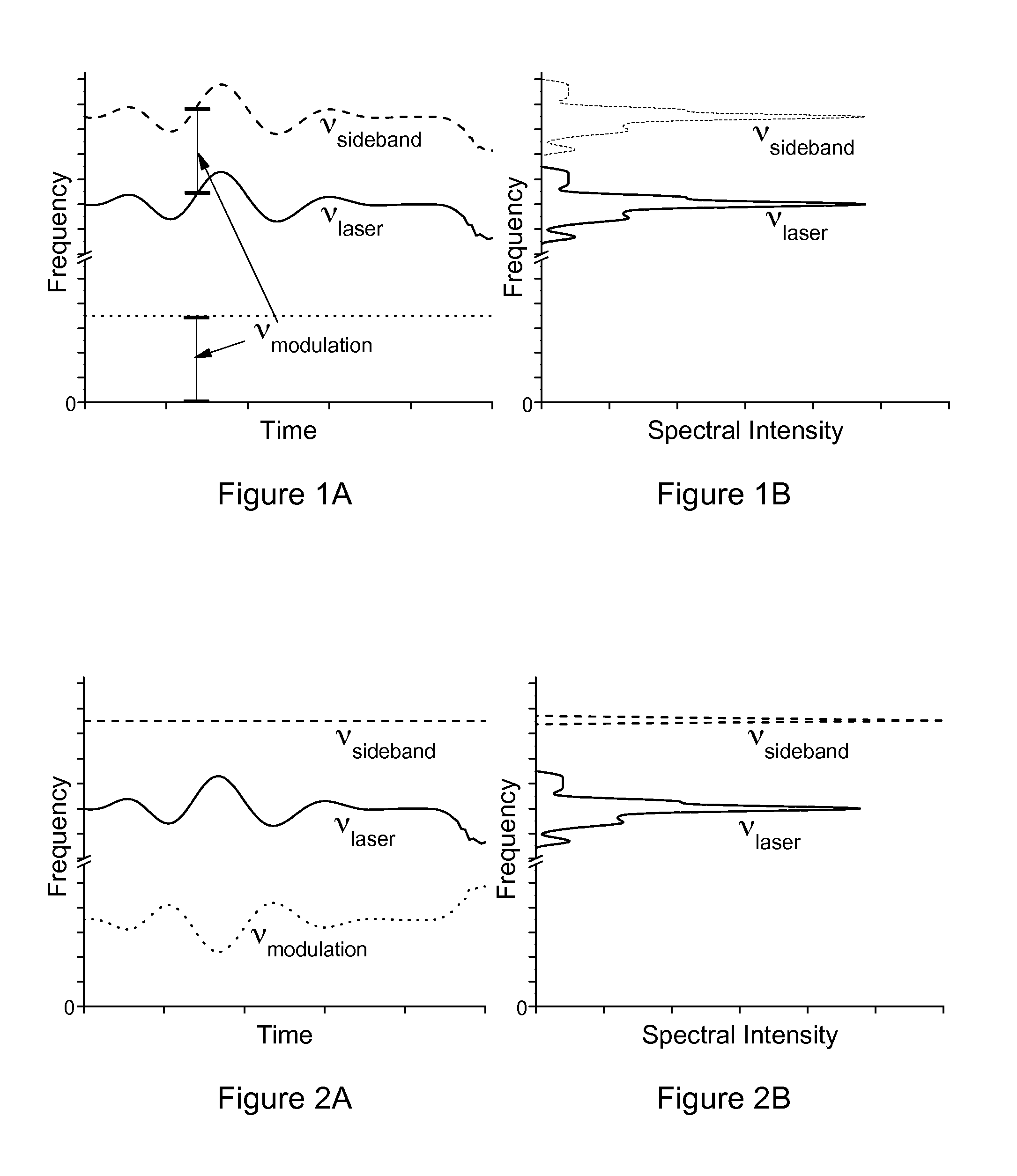
[0032]The theory of operation of sideband locking according to the invention is described below with reference to FIGS. 1A, 1B, 2A and 2B. The frequency of laser emission, νlaser, varies in time, as indicated by the solid curve in the graph of FIG. 1A. Rapid variation in the frequency of laser emission is often called “jitter” and slow variation is called “drift.” The laser emission observed over a time long enough to see the variation has a non-trivial spectrum with a non-zero spectral linewidth, as indicated by the solid curve in the graph of FIG. 1B.

[0033]Applying an external phase or frequency modulation with frequency νmodulation creates sidebands at frequencies νlaser+m*vmodulation, where m is one or more integers. If this modulation frequency is fixed, as indicated by the dotted curve in the graph of FIG. 1A, then each sideband is a duplicate of the original laser emission spectrum shifted by m*νmodulation. In sideband locking CEAS according to the invention, the frequency in...


PUM


Abstract

A cavity enhanced absorption spectrometer (CEAS) and method for controlling the same. The CEAS includes a coherent electro-magnetic radiation source, an electro-magnetic modulator that creates a sideband with an adjustable frequency that is offset from the radiation source frequency by imparting an adjustable frequency modulation to the radiation. The CEAS also includes a RF source that drives the electro-magnetic modulator and a cavity enhanced absorption resonator (CEAR) that receives the sideband. A detector measures the proximity of the frequency of the sideband relative to the resonant frequency of the CEAR and generates a proximity detector signal, which is converted by a controller to a control signal that controls at least one of the RF source and the resonant frequency of the CEAR such that the frequency of the sideband and the resonant frequency of the CEAR are adjusted to maintain a predetermined proximity therebetween.

Description

BACKGROUND OF INVENTION[0001]1. Field of Invention[0002]The present invention relates to a cavity enhanced absorption spectrometer and a method for controlling the same.[0003]2. Description of Related Art[0004]Cavity enhanced absorption spectroscopy (CEAS) is a linear optical absorption spectroscopy. It uses an optical resonator with very low optical loss (e.g. high finesse) to trap circulating optical radiation for many round trips, thus increasing the effective path length traveled by the radiation, typically by a factor of several thousand times the physical length of the resonator. This length enhancement factor also applies to the optical absorption sensitivity, making CEAS an extremely sensitive detection technique. Cavity ring-down spectroscopy (CRDS) is a common type of CEAS in which the optical injection is periodically interrupted, and the exponential ring-down of radiation exiting the CRDS resonator is measured.[0005]CEAS requires injecting optical radiation into the reso...

Claims


Application Information

Patent Timeline
IPC IPC(8): G01J3/02
CPCG01J3/0237G01J3/4338
Inventor MCKEEVER, JASONMILLER, ANTHONY EDWARD
Owner ENTANGLEMENT TECH
Learn More