Flyback type snubber circuit

a snubber circuit and circuit technology, applied in emergency protective circuit arrangements for limiting excess voltage/current, and emergency protective circuit arrangements, etc., can solve the problems of slow speed, slow speed, and fast speed of conventional switching devices, and achieve the effect of minimizing the loss attributable to switching

Inactive Publication Date: 2014-10-30
IND COOP FOUND CHONBUK NAT UNIV
View PDF1 Cites 1 Cited by
  • Summary
  • Abstract
  • Description
  • Claims
  • Application Information

AI Technical Summary

Benefits of technology

[0011]Accordingly, the present invention has been made keeping in mind the above problems occurring in the prior art, and an object of the present invention is to provide a flyback type snubber circuit capable of minimizing a loss attributable to switching.

Problems solved by technology

The IGBT, that is, a conventional switching device, is fast in speed, but is problematic in that it has a small capacity.
In contrast, the GTO thyristor has a high capacity, but it is disadvantageous in that speed is slow.
The trend of a medium voltage power conditioning system should be increased in capacity and precisely driven at high speed, but the conventional IGBT and GTO thyristor are no longer suitable for such a trend.
If the IGCT is used, however, there is a problem in that a switching device is damaged by overvoltage or overcurrent that is instantly generated.
The resistor RS causes an energy loss, thereby deteriorating efficiency of a medium voltage power conditioning system.
Furthermore, there is a problem in that the total size of the system is increased due to the resistor RS and the capacitor CCL.

Method used


Image

  • Flyback type snubber circuit
  • Flyback type snubber circuit

Examples


Embodiment Construction

[0021]An exemplary embodiment of the present invention is described in detail with reference to the accompanying drawings.

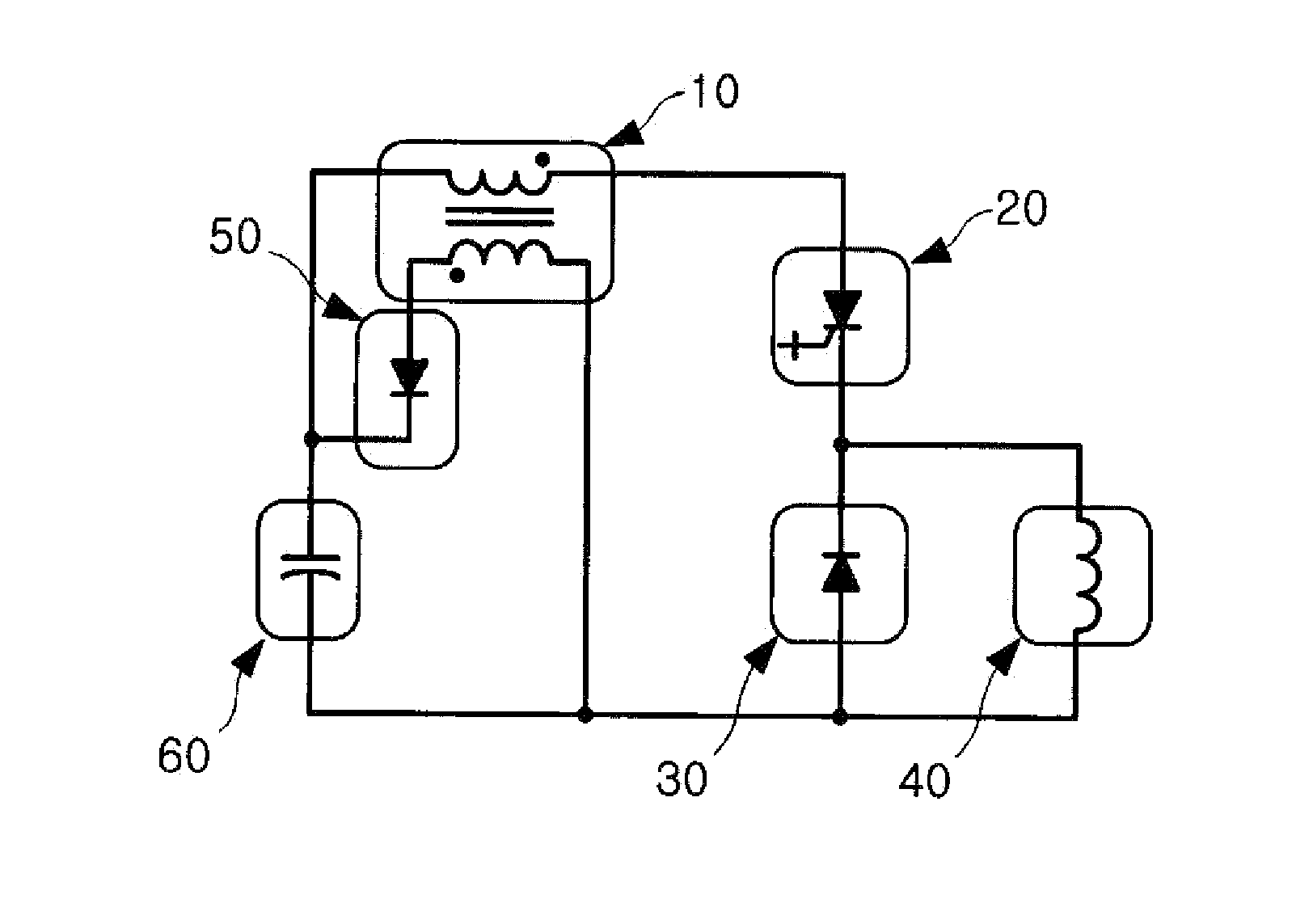
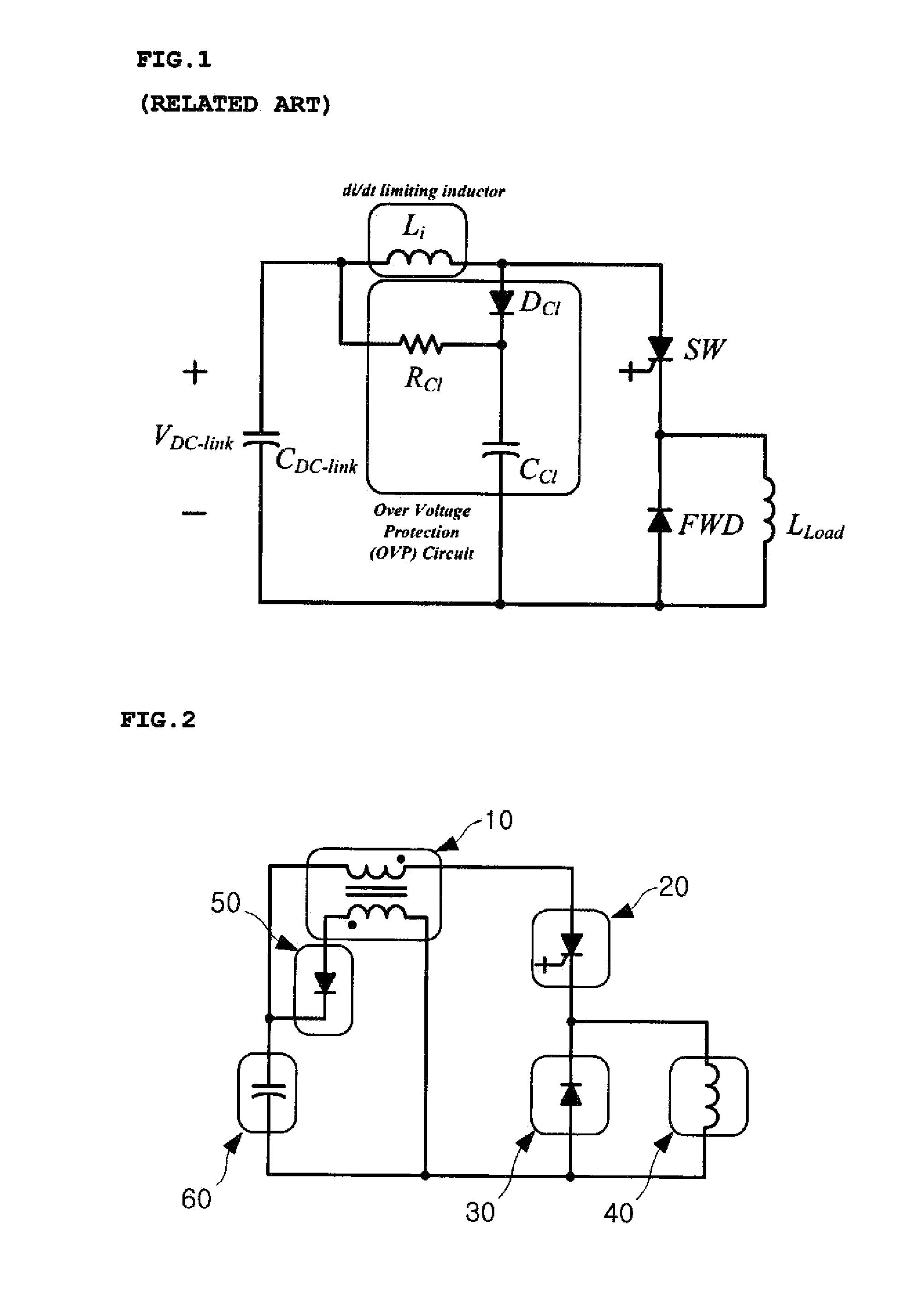
[0022]FIG. 2 is a circuit diagram showing an IGCT protection circuit including a flyback type snubber circuit of the present invention.

[0023]The flyback type snubber circuit of the present invention includes transformer 10 and a diode 50. The transformer 10 has a primary side connected between an input power source 60 and a switch and a secondary side connected to the diode 50. The diode 50 is connected between the input power source 60 and transformer 10.

[0024]If a power semiconductor 20 used as the switch is in the on state, an electric current flows from the input power source 60 to a power semiconductor 20, a free-wheeling diode 30, and a load inductor 40 via the primary side of the transformer 10. If the switch shifts from the on state to the off state, an electric current from the input power source 60 no longer flows into the rear of the power semiconducto...


PUM


Abstract

A flyback type snubber circuit includes an transformer configured to have a primary side connected between a power source and a switch and have a secondary side connected to a diode. The diode is connected between the power source and the transformer.

Description

CROSS REFERENCE TO RELATED APPLICATION[0001]The present application claims the benefit of Korean Patent Application No. 10-2013-0047448 filed in the Korean Intellectual Property Office on Apr. 29, 2013, the entire contents of which are incorporated herein by reference.BACKGROUND OF THE INVENTION[0002]1. Technical Field[0003]The present invention relates to a flyback type snubber circuit, and more particularly, to a flyback type snubber circuit configured to function as an auxiliary circuit for protecting a semiconductor device used in a medium voltage power conditioning system.[0004]2. Description of the Related Art[0005]A switching device used in a medium voltage power conditioning system is turned on or off in response to a switching device driving signal from a gate driver. In general, the switching device has been implemented using a Gate Turn-Off (GTO) thyristor or an Insulated Gate Bipolar Transistor (IGBT).[0006]The IGBT, that is, a conventional switching device, is fast in s...

Claims


Application Information

Patent Timeline
Patent Type & Authority Applications(United States)
IPC IPC(8): H02H3/20
CPCH02H3/20H02M1/34Y02B70/10H02M1/346H02M3/28H02M3/22H02M1/42
Inventor SUH, YONG SUGLEE, KI HYUNJUNG, KYUNG SUB
Owner IND COOP FOUND CHONBUK NAT UNIV
Why Eureka
Try Eureka